Daily news, dev blogs, and stories from Game Developer straight to your inbox
Sponsored By
Featured Blog | This community-written post highlights the best of what the game industry has to offer. Read more like it on the Game Developer Blogs or learn how to Submit Your Own Blog Post
Writing a Game Engine from Scratch - Part 4: Graphics Library
Writing an Engine from scratch can be a daunting task. In this Part we delve into depths of Graphics Library Programming. We look at how to write our own Rasterizer in order to understand fully how to use OpenGL/DirectX and possibly Vulkan to full extent!
42 Min Read

Part 1 - Messaging
Part 2 - Memory
Part 3 - Data & Cache
Part 4 - Graphics Libraries
This Article is stand-alone and can be read without the previous parts. While Programming knowledge or familiarity with OpenGL isn't a must to continue reading, it can be helpful. I'll assume some basic familiarity with general 3D Rendering or Modelling (What are Polygons, Textures, Vertices? - type of knowledge). The accompanying Code can be found here.
"Yes! We've finally reached the part about Graphics! Let's get some epic Scenes and Special Effects going!"
- Someone on the Internet I made up
... or at least he might have thought. But by now I hope you realized, that this isn't how we do things in this Series.
At this stage, it would seem rather logical to discuss Graphics Libraries like OpenGL and DirectX and perhaps compare their Pros and Cons. We might even take a look at some simple OpenGL examples and see how we move on from there to "real" Game Graphics. After all, it would be rather simple to explain a "Hello Triangle" using OpenGL / DirectX and tell the reader, that all he needs to do now to make a simple Game is to add more Triangles and some logic to move them.
But we aren't here to do simple! We are here to learn the real meat. The dirty details.
Therefore, the goal of this Article isn't "how to use OpenGL/DirectX". Instead, our goal will be "how to create OpenGL/DirectX".
I believe, if you understand the inner workings of a 3D Graphics Library, a lot of things become much clearer (Probably the coolest (yet slightly dated) book on this Subject is a 1728 page Tome from the year 2003 by André LaMothe). I hope a sort of intuition will develop when thinking about modern Computer Graphics. No longer will you simply copy-paste OpenGL snippets from StackOverflow without knowing why and how they work. From now on, you will copy-paste them, knowing why they work. Which is good enough in my book.
We want to develop the Rendering Pipeline here. All Graphics that we Render are just a proof of concept meant to illustrate the inner workings and not the main focus.
Graphics Libraries are a huge Subject, far too big for a single Article. We will be skimming a lot of topics. I hope we can revisit them at a later point or point you to some excellent resource on the web.
The most prominent Graphics Library APIs are without a doubt OpenGL and DirectX. Therefore, this Article will mainly focused on implementing a small subset of OpenGL ourselves. We choose OpenGL as it applies to a broader scope of applications. But don't worry, most of what follows should hold true for DirectX as well.
But what does a Graphics Library do?
In short, a Graphics Libraries (GL) only job is to display Graphics of all shapes and sizes. It just displays what you tell it to display. Want to draw a line? There it is. A rotated Triangle? Voila! Want to give it some Color? No Problemo!
A GL in itself is pretty dumb. It doesn't really understand the concept of Lighting or Animation or even Camera movement. All these things we must feed it ourselves. Instead, what a GL does is give us all the tools and freedom we need to do whatever we want graphically. (We ignore historic methods like T&L Units)
What makes OpenGL and DirectX so special, is that they use Hardware (Graphics Card, Embedded Graphics, ... ) to accelerate all the drawing. The Code / Implementation for OpenGL / DirectX is actually in the Hardware specific Driver. Therefore, calling OpenGL functions results in working almost directly with the Driver. This also means, that these functions could be implemented differently for every single Graphics Card Series.
Thanks to the standardization of OpenGL and DirectX versions, we at least know they will do the same thing on each platform. Or at least they should. It has become pretty common practice for Hardware vendors to optimize certain routines specifically for a Game. If you've ever wondered, how a simple Driver update can cause massive speed gains in modern Games, this is it. This sadly can lead to some unwanted side effects. But this is not our Focus here - let's move on.
In the "old days" (a few years back) a lot of games featured something called a "Software Renderer" or "Software Rasterizer" as an option. It was basically a purely CPU based implementation of
a Graphics Library, meant for PC's without a dedicated Graphics Card. It could do all the same things, but was extremely slow for obvious reasons.
So let's write a Software Renderer and pretend we are doing it on the Hardware!
We won't write our own mini-OpenGL implementation using Hardware Acceleration. That would be insane. Thus we will write a purely CPU based GL, that we will call sGL and will be based heavily on how things are done in OpenGL. We will simply pretend that our code runs on the Graphics Card.
All the Code will be available here . Don't worry, I'll try to convey most of the things in words instead of code. But a few code snippets will apear here and there. It is written in simplistic and very bad C++. I tried to write it as short and understandable as possible. So yeah, Globals... naked pointers... no classes... like a 7 year old.
We will try and stick as close to the overall OpenGL picture / API as possible. For example, where OpenGL might have a function called glBindBuffer(), we will have sGLBindBuffer().
But where to Start...
Let's set our goal to display textured, alpha blended and shaded Triangles using our sGL.
What do we need to start? Some way to draw Pixels to the screen. This isn't as trivial as it might seem in portable C++. For this reason we will use the SDL Library just for drawing multiple Pixels at once to the screen - nothing more, nothing less - otherwise this whole project would take forever. Yes, SDL uses OpenGL under the hood to draw, but we will just ignore that.
If all we have is a method to draw dots on a screen, how can we end up with actual Triangles?
As an exercise, you could spend some time and think about how you would draw a plain color Triangle on the screen, with nothing more than a setPixel() function and 3 Points defining the Triangle corners.
It seems so straight forward. On paper, you could draw your 3 Points, connect them and fill in the middle. But doing that on the Computer with nothing but a setPixel() function isn't as obvious as it seems. We will explore the answer soon.
The Actual Render Pipeline
Let's take a quick look at a very simple diagram illustrating the most important aspects.
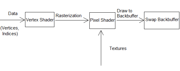
The overall idea is simple:
We start with Vertices that describe our Triangle (3 Positions, Color, Texture Coordinates...)
We pass those Vertices to the Graphics Card
The Graphics Card can do some neat calculations on those Vertices - Transformations mainly (Vertex Shader)
So far we have 3 Points. The Graphics Card now fills those 3 Points to form a Triangle (Rasterization)
Each Pixel inside the Triangle can now be shaded (Pixel Shader)
We draw the Pixels to the Backbuffer, as well as perform some Depth Tests, Alpha Blending, etc.
We draw the Backbuffer to the Screen
We will use this List as a guide to proceed and look at individual topics in a bit more depth.
1. and 2. Vertices, Indices, Textures and Uniforms
Nowadays, if we want to do Graphics, we need to get the Graphics Card involved. This also means, we need to store everything we want to display on the screen accessible enough for the GPU to address it directly. Usually this would be the Graphics Card own Video Memory (or the shared Memory for embedded Graphics).
We therefore have to send (or at least flag) everything we have stored on our RAM that we want to draw. This includes, but isn't limited to
Vertices - Describing the Geometry of our Triangles
Indices - Describing the relation between the Vertices
Textures - Giving our Triangles some much needed Color
"Uniforms" (Sticking with OpenGL terminology) - Small bits of information we might need, like Matrices, Special Parameters and even Lighting
Usually, the process for this is simple. We tell our Graphics Library that we need to reserve some Space on the Graphics Card and then send it the information whenever we please.
Let's just take an exemplary look at how we do this in OpenGL and how we wish to do it in our own sGL.
OpenGL | Description | sGL |
|---|---|---|
glGenBuffers() | Generates a unique Buffer ID the User can identify his Buffer by | sGLGenBuffer() |
glBindBuffer() | Creates a new (empty) Buffer with the supplied ID or uses an existing Buffer by that Buffer ID. | sGLBindBuffer() |
glBufferData() | Creates and Initializes a buffer with the supplied Size and Data | sGLBufferData() |
The OpenGL specification is quite liberal with how these things are implemented. We will be very simplistic with sGL. So simplistic in fact, that we will not even bother creating a class and store everything in GLOBALS! HA!
Generating Buffer ID's? We just keep track of what the last ID was we issued and simply increment it each call.
Binding Buffers? We just store the Buffer ID we currently use in some global int. Let's call that g_sGLBoundBuffer.
Creating and Initializing Data? Well, Remember the Article on Memory Management? This applies to Video RAM the exact same way. But let's stay simple and do a dirty new operation.
void sGLBufferData(int size, in_out_vertex_t * vertexData)
{
	g_sGLVertexBuffer[g_sGLBoundBuffer] = new in_out_vertex_t[size];

	for (int i = 0; i < size; ++i)
	{
		g_sGLVertexBuffer[g_sGLBoundBuffer][i] = vertexData[i];
	}
}
Pretty easy if you don't care about Memory Management, huh?
Now obviously we hard-coded a lot of things. For example, OpenGL allows you to specify your own Data Layout for each Vertex. We stuck to a specific one called in_out_vertex_t. OpenGL also allows you to generate any type of Buffer with the above calls. We stuck to Vertex Buffers.
But that's okay! We are just here to see how it could be done to get a feeling for the broader picture. Creating Index Buffers and Texture Buffers would be quite similar.
But you may have noticed the first thing...
Memory Management?
Yes, OpenGL does not give you the option to specify exactly how things are stored in detail. We can do it now in our own GL but normally it's all hidden behind those Buffer calls. This can become a problem when moving / deleting / creating large Chunks. Memory Management can become a pain, especially for Textures.
But this will Change once Vulkan arrives and should be part of DirectX 12.
Shader Code
What exactly the Shaders do will be discussed later. For now it's safe to assume that they are made up of Source Code and is just another Piece of Data that has to reach the Graphics Card. This Shader code will initially reside on the Main RAM until specifically send and bound using the following functions.
OpenGL | Description | sGL |
|---|---|---|
glCreateShader() | Creates an empty Shader (any Type) and returns a unique ID for us to reference it by | - not needed, our Shader is on the CPU - |
glShaderSource() glCompileShader() | Loads the Source Code onto the Graphics Card and Compiles it | - not needed, our Shader is compiled with the main Program - |
glAttachShader() glLinkProgram() | Combines Vertex / Pixel Shaders into on single Shader Program | - not needed, we are interestingly more flexible - |
glUseProgram() | We define what Shader Program we want to use for our Rendering | sGLUseVertexShader() sGLUsePixelShader() |
In our own Implementation all we have is a simple sGLUseXXXShader() function. It does nothing more than store a function pointer to the current Shader we wish to use.
// Some Shader Code
in_out_vertex_t vertexShader(in_out_vertex_t inVertex)
{
	in_out_vertex_t out = inVertex;

	// Do something

	return out;
}

// The currently used Shader
in_out_vertex_t(*g_sGLVertexShader)(in_out_vertex_t);

// And Binding our Vertex Shader
void sGLUseVertexShader(in_out_vertex_t(*inVS)(in_out_vertex_t))
{
	g_sGLVertexShader = inVS;
}
Nothing all too fancy. If you aren't familiar with Function Pointers, that's fine. All that happens is that we store which Shader to use in g_sGLVertexShader.
Now the interesting part here is what happens in OpenGL - glShaderSource() and glCompileShader(). In OpenGL, the Shader Code is compiled after it is send to the Graphics Card. This means, you have no direct control over the compile process once your Game has shipped. It's equivalent to sending the source code of your game to the Player and pray that his Compiler does the exact same optimizations as yours did.
Now, there are ways to send the Shaders pre-compiled in OpenGL (glShaderBinary() comes to mind). But I am not aware of any portable methods - you'd have to create those binaries for each system you wish to support separately. Not fun.
3. Draw Call
Now, we have all the data on our Graphics Card, it's time to draw! What happens first? Obviously, the user has to issue some commands.
He tells the Graphics Card exactly what he wishes to use. He binds his Vertex Buffers, uses his Shader Program, sets his Textures... He also enables any additional things he wishes to use, like Alpha Blending, Depth Testing...
Then he tells OpenGL to Draw! Let's focus on one of the possible draw functions OpenGL provides:
OpenGL | Description | sGL |
|---|---|---|
glDrawElements() | Renders some number of Primitives / Polygons that have been specified in the Buffers. | sGLDrawElements() |
For us, this will be the main drawing call. How do we implement this?
Well, for one, this draw call can specify how many Triangles (or Primitives in general) we actually want to render via count. So in our function, we will need to loop through count-Elements and draw them. For testing purposes, imagine this (wrong) snippet:
void sGLDrawElements(int count)
{
	// We loop each Triangle we need to draw
	for (int i = 0; i < count; ++i)
	{
		drawLine(
		g_sGLVertexBuffer[g_sGLBoundBuffer][i*3],
		g_sGLVertexBuffer[g_sGLBoundBuffer][i*3 + 1]);

		drawLine(
		g_sGLVertexBuffer[g_sGLBoundBuffer][i*3 + 1],
		g_sGLVertexBuffer[g_sGLBoundBuffer][i*3 + 2]);

		drawLine(
		g_sGLVertexBuffer[g_sGLBoundBuffer][i*3 + 2],
		g_sGLVertexBuffer[g_sGLBoundBuffer][i*3]);
    }
}
This would basically draw a Wireframe of our Triangles, if we simply ignore the z-coordinate for now. I'll just leave the above snippet here as a simple look at how simple all this could be if we were stuck in Battlezone style Games. (Image taken from this wiki)
But how do we address the points we want to draw?
The Screen
Let's just assume that our Screen has two sets of coordinates. The set that interests us most is the set of coordinates that are fixed to the floating point range of -1 to +1 (can be customized, but I like to stick to -1 and +1) in both the x and y direction. These are pretty ideal for 3D use.
We also have a set of coordinates that are used to actually address individual Pixels, mostly known as the Resolution. For example the whole number range of 0 to 1024 in width and 0 to 768 in height. These numbers are hard to work with and are only used when we actually need to address discrete Pixels.

Let's stick to the -1 to +1 range for our Screen. If we were to draw Wireframes of Vertices with coordinates outside of the -1 and +1 boundaries, they wouldn't be visible. This is known as Clipping, pretty straight forward. It's wise not to waste processing power on doing any useless operations on Areas that have been clipped. For our Wireframe, this would mean that the drawLine function would simply exit once it notices it has left the bounds.
Just some things to keep in mind for our next Section.
3. Continued - Vertex Shader
Looping through the same list of Vertices and drawing the same Wireframe every frame is rather boring. We want fully textured and moving Triangles! Textured Triangles we will come to later. Let's see how we can move them.
What we want is translation, rotation, scaling or in general, transforming our Triangles. We might also want to apply some Color information to each Vertex or play with the u,v-coordinates. So, why not just pass each Vertex through a custom function that will do those operations for us?
That's the Vertex Shader. In our little sGL it might look like this:
in_out_vertex_t vertexShader(in_out_vertex_t inVertex)
{
	in_out_vertex_t out = inVertex;

	out.x = out.x * 2.0f;
	out.y = out.y * 2.0f;
	out.z = out.z * 2.0f;

	return out;
}
Such a Vertex Shader would scale each Vertex out from the origin by a factor of 2. Nothing fancy. But if we add it to our sGLDrawElements method, we can assure that every Vertex currently being drawn has to go through this Shader! (Recall that we stored a reference to the above function in a function pointer called g_sGLVertexShader)
void sGLDrawElements(int count)
{
	// We loop each Triangle we need to draw
	for (int i = 0; i < count; ++i)
	{
		in_out_pixel_t resultTriangle[3];

		// First, we Apply the Vertex Shader to each of the 3 Vertices
		for (int j = 0; j < 3; ++j)
		{
			in_out_vertex_t currentVertex;

			currentVertex =
			g_sGLVertexShader(g_sGLVertexBuffer[g_sGLBoundBuffer][i * 3 + j]);

            resultTriangle[j] = convertTo_in_out_pixel_t(currentVertex);
		}

		// Do other Stuff with the resultTriangle here,
		// like drawing the Wireframe
    }
}
We store the Triangle we have passed through the Vertex Shader as resultTriangle, containing the 3 transformed vertices. For future use, resultTriangle has a different Format, that we won't bother with now.
With this System in place we just need to alter the Vertex Shader source code to play with every Vertex at once. Neat.
World, View, Projection
(Note: I'll just give a brief overview of these concepts here, the concrete details aremostly technical and not too interesting for us at this moment, as we are developing the framework to render Graphics. Here is a nicely formatted Article that goes into more details)
We remember that large memory operations are expensive. So it makes sense that instead of adding or multiplying a small number to every Vertex in our Buffer just to move the Scene, we can simply do this little operation in the Vertex Shader, without changing the data in memory!
This Transformation is usually called World Transformation. If you want to alter the size, position or rotation of the World on the fly, it's easiest done in the Vertex Shader.
Now, a ever changing World is cool enough, but we will most likely still see the same thing on the Screen the whole time. After all, we are still rendering the same screen space (-1 to +1 for x and y coordinates) as before. We only render something interesting if its position happens to be inside the bounds of our screen coordinate system.
Artificially changing the screen coordinate system to see more of the world would be a strange thing to do (but not unheard of). So instead, why don't we keep shifting the World so that the interesting bits happen to be in our -1 to +1 range? This is called a View Transformation.
Now, we have ignored the z-coordinate thus far. Once we activate that, we suddenly get the notion of "front" and "back". We will simply define everything with a positive z coordinate as being in front of us and everything with a negative z-coordinate as being behind us.
Everything with a negative z-coordinate will simply be ignored when we draw.
But what if we want to see what is behind us? Well, we can translate it until it is in front of us or we rotate it.
Boom - we have a Camera that we can move in our World. And all this is done in our Vertex Shader!
But wait. Something seems off... it's all... flat. There seems to be no depth, even though we have activated our z-coordinate!
The simple fact remains, our flat 2D Screens know nothing about depth. We have to artificially create depth. Actually what we have been doing (unintentionally) thus far is known as orthographic projection. What we actually want (not always, but mostly in 3D) is perspective projection. I believe an Image should clarify the difference best (Taken from the Blender Manual).
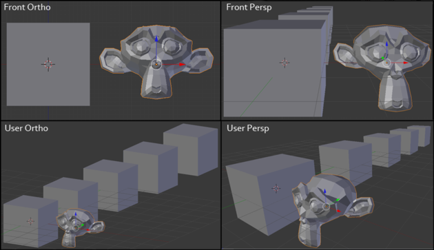
Left we have Orthographic Projection and on the right we have Perspective Projection. Left is "flat" and right has "depth".
How does this effect happen? How do we generate it ourselves? Well it's rather "simple" to fake it. Basically the further away things are (higher z-coordinate), the smaller they get. This would be equivalent to simply dividing the x-and y-coordinates by their z-value (and some other mathematical operations).
We can do this in the Vertex Shader! It's called the Projection Transformation.
These 3 Transformations can be concisely written as Matrices acting on (i.e. multiplied by) our Vectors. You will almost certainly see this in every Vertex Shader. It might look like this:
in_out_vertex_t vertexShader(in_out_vertex_t inVertex)
{
	in_out_vertex_t out;

	out = inVertex * worldMatrix * viewMatrix * projectionMatrix;

	return out;
}
(We are lazy in sGL and don't use Matrices. Our main focus is the Pipeline, not fancy Graphics. We just do it by hand, as you will see in the source code.)
More can be done in the Vertex Shader! After all it's called a Shader, so we can color the 3 Vertices of our Triangle, if our Vertex structure carries color data. Or even alter Texture coordinates.
Backface Culling
At this stage, it makes sense to weed out some Triangles that don't make sense to draw. For Volumetric Models, it can be wise to ignore all Triangles that "face away".
This is called Backface Culling. Usually, to determine which Triangle is showing it's backface, is to simply check if the newly calculated Vertices are in Clockwise or Counter Clockwise order.
These can be set quickly via glEnable(GL_CULL_FACE), and glCullFace / glFrontFace calls.
Generally it makes sense to set this once and keep it consistent throughout the Project. For our sGL, we will ignore this feature.
4. Rasterization
So far we've been creating Wireframes. Boring. We want filled Triangles!
Scan Lines
One trick used to draw Triangles on the computer is to use a method called scan lines. Basically, you traverse the edges of the Triangle (A) and start drawing a horizontal line at each step until you hit another edge (B).
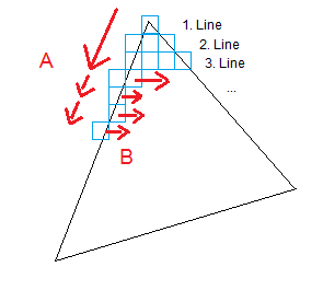
This method isn't all too complex and can be done quickly. To deal with the odd shape of Triangles, a common trick is to split the Triangle into two halves, each with a horizontal bottom or top. For details on this method I'll refer to this article. The code in that article is also used in our sGL method.
It's interesting to note, that the original Scan Line method traverses the whole screen from left to right. Once it hits the first edge of our Triangle, it starts filling in the Pixels and only stops, once it hits another edge. For Triangles, the Scan Line can stop here. What's interesting about this is, if we should continue the Scan Line and hit another Edge, we start drawing Pixels again until we hit another edge. This would allow us to draw more complex Polygons of any shape, not just Triangles. But we won't need this method, we will just concentrate on Triangles and the sped up version illustrated in the previous paragraph.
Now, to save further processing power, we won't be drawing the Wireframe anymore. After all, the Wireframe is just the first and last pixel of our Scan Line method and gets filled anyways.
But what do we do with the Pixels we have determined that are inside the Triangle via our Scan Line method? What Color should we draw them? Perhaps the one defined in one of the Vertices?
We could. If we do, we would have a 3D World filled with single colored Polygons. Doesn't seem exciting? Games like F/A-18 Interceptor would disagree.
Furthermore, un-textured flat shaded Triangles (i.e. single color) seem to be having a renaissance! But we are greedy. We want Textures and Lighting. And we want it to apply for every Pixel we scanned.
Why not use the same trick we did with Vertices and feed each Pixel into a function that applies all these effects? Well, we might just do that. Voila, Pixel Shaders!
But before we dive into Pixel Shaders, we need to do some preparing. Simply knowing what Pixels we want to draw isn't enough. We need some more information for that Pixel to work with.
We don't just need the Screen Space Position of the Pixel we wish to draw, we will also need to know where that Pixel is in relation to it's Triangle! Otherwise we can't apply Textures.
We need some sort of Coordinate System for the Triangle itself. This is actually a bit tricky and not very straightforward to get. We will be using Barycentric Coordinates for our Triangle. To my knowledge, these are used by most OpenGL implementations under the hood.
Barycentric Coordinates
Barycentric Coordinates can give each Vertex of our Triangle a "weight" of how close the Pixel is to it. This makes it very easy to interpolate the values that are associated with that Pixel from the Vertices.
For Example: Say each Vertex of your Triangle has a different color. Blue, Red and Green. What Color does a Pixel in the middle of the Triangle have?
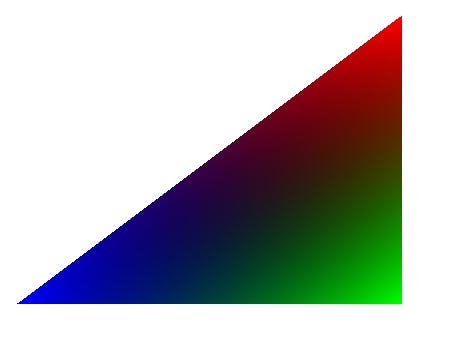
We need to interpolate! Between 2 Points this would be easy, but on an area between 3 Points? Barycentric Coordinates are the answer!
I will not bore you with the mathematical details behind barycentric coordinates, but rather we will take an intuitive look at it.
For our interpolation, we need some way to determine how "close" we are to one of the 3 Vertices. Perhaps in percent, so we know how much of each Vertex we add to the final outcome.
Let's take a look at following picture:
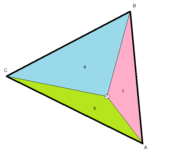
We have a Triangle made up of 3 Vertices, A, B and C. Inside this Triangle, we have a Point of interest (white circle). From this Point of interest, I've drawn 3 helper lines connecting it with the Vertices. These helper lines form a new set of 3 Triangles within our original Triangle, a (blue), b (green) and c (red). I've named these areas according to the Vertex that is on the opposite side. For example, area a (blue) is on the opposite side of Vertex A.
Now, the Point of interest in the picture above is closer to Vertex A than to the other Vertices. Notice how area a is also bigger than the other areas b and c. Imagine the Point being even closer to A, then area a would be even bigger!
Let us use this correlation between the area of a and the closeness of the white circle to Vertex A to our advantage.
The entire area of the Triangle is just (a + b + c). This means, a / (a + b + c) gives us the percentage of area that a covers in respect to the entire Triangle. We also saw earlier that this was in relation to the closeness of our Point of Interest to Vertex A. Now we have that closeness in percent. This is exactly the value we were looking for! Let's call these values lambda.
lambda1 = a / (a + b + c)
lambda2 = b / (a + b + c)
lambda3 = c / (a + b + c)
We can now easily interpolate anything on our Triangle using these weights. For example, let's take the color. If we have a different Color defined for every Vertex, we could interpolate red as follows:
result.red = lambda1 * A.red + lambda2 * B.red + lambda3 * C.red
Easy!
(Note: To get the areas, the easiest way would be the using the cross-product. Halving the length of the resulting vector of the cross-product results in the area size of the Triangle that is spanned by the two input vectors. In our little sGL we use a different - faster - method due to laziness, presented in this StackOverflow answer here.)
Interpolating
We can now interpolate every value that is defined discretely at the 3 Vertices of our Triangle. Color, Texture Coordinates, even the z-coordinate!
OpenGL has a build in way of letting the user add more variables to the List of things that get interpolated: varying (old) and the in / out qualifiers. Use them, now that you know what happens! Don't try to interpolate things yourself, if you can let the Hardware do it for you.
Now, we have all the information to plug it into our Pixel Shader - g_sGLPixelShader. Our Scan Line function sGLScanLine might look like this:
void sGLScanLine(int x0, int x1, int y, in_out_pixel_t * tris)
{
	// We scan from left to right, so we determine which is which

	int sx = x0 < x1 ? x0 : x1;
	int ex = x0 < x1 ? x1 : x0;

	// sx = left edge --- ex = right edge
	for (int x = sx; x <= ex; ++x)
	{
		in_out_pixel_t currentPixel;
		float lambda1, lambda2, lambda3;

		calculateBarycentric(x, y, tris, &lambda1, &lambda2, &lambda3);

		currentPixel.x = x;
		currentPixel.y = y;

		// We can then interpolate the Color, uv and z coordinate
		// across the Triangle

		currentPixel.color.r = tris[0].color.r * lambda1
			+ tris[1].color.r * lambda2 + tris[2].color.r * lambda3;

		currentPixel.color.g = tris[0].color.g * lambda1
			+ tris[1].color.g * lambda2 + tris[2].color.g * lambda3;

		currentPixel.color.b = tris[0].color.b * lambda1
			+ tris[1].color.b * lambda2 + tris[2].color.b * lambda3;

		currentPixel.color.a = tris[0].color.a * lambda1
			+ tris[1].color.a * lambda2 + tris[2].color.a * lambda3;


		currentPixel.u = tris[0].u * lambda1 + tris[1].u * lambda2
			+ tris[2].u * lambda3;

		currentPixel.v = tris[0].v * lambda1 + tris[1].v * lambda2
			+ tris[2].v * lambda3;


		currentPixel.z = tris[0].z * lambda1 + tris[1].z * lambda2
			+ tris[2].z * lambda3;


		// We feed this Pixel information into the Pixel Shader
		currentPixel = g_sGLPixelShader(currentPixel);

		// And finally draw the Pixel onto the Back Buffer
		sGLSetPixel(currentPixel.x, currentPixel.y, currentPixel.z,
			currentPixel.color);
	}
}
5. Pixel Shader
We have all the information we need inside the Pixel Shader to do some Fancy Shading.
Usually this involves a minimum of applying the Texture and overlaying that with some simple shading color. Let's start with a basic look at Texturing.
Texturing
In the Pixel Shader you have access to Textures loaded on the Graphics Card. There is nothing magical going on here. You can access parts of the Texture via the u,v-coordinates that we interpolated earlier. Or any type of coordinates you wish.
The interesting part about Texture Access is, how the access request is handled. The different sampling techniques are often referred to as Texture Filters and can be set via the OpenGL command glTexParameter().
What this basically comes down to are two things:
The u,v-coordinates (mostly in the range of 0.0 - 1.0) do not correlate to an exact discrete point on the Texture.
The Pixel we are currently shading might actually cover larger portion of a texture
Dealing with the first is rather easy. For example, on a simple 3 x 3 Texture, we could define that the u-coordinates 0.0, 0.5 and 1.0 correspond to the center Points of the Texture-Pixels (Texels). Any value in between (like 0.25) would either need to correspond to it's nearest neighbor (Point Sampling) or need to be interpolated between the neighbors. Common Filtering methods here are, Bilinear Filtering (Linear Interpolation in the u,v-directions) and Bicubic Filtering (Cubic Interpolation in the u,v-directions).
Short Detour: Affine Texture Mapping
Let's give Point Sampling a shot in our sGL! We shall use the following simplistic texture:

Let's also apply some shading colors and slightly rotate the Triangle for some depth effects, just to see if everything is working. And here is what it looks like:
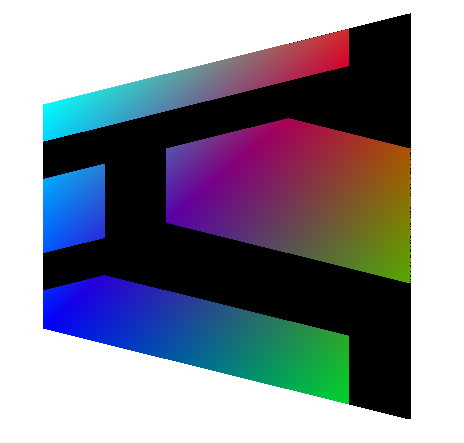
Wait... That looks... well, crap. Why is it so distorted? Did we mess up our Barycentric coordinates?
You'll be relieved to hear that we didn't mess up our coordinates. Not entirely. What you see here is often referred to Affine Texture mapping. It is an effect that is very prominent in older 3D Games to speed up rendering, like on the Playstation 1 or on Software Rasterizers for Quake and such.
But what we really want is perspective correct Texture mapping -> Projective Texture mapping. Just look at these two mapping techniques side by side.
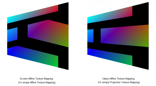
Ahhh, so much nicer! So, again, what did go wrong?
It is actually hinted at in the name of the two mapping techniques. Affine. For us it suffices to know that an Affine Transformation is a Transformation that preserves parallel lines (and some other things). If two lines were parallel before an Affine Transformation, they are still parallel after it.
I've called one "Screen-Affine" and one "Object-Affine". The reason behind this is simple:
From the point of view of the Screen, the "Screen-Affine" Texture Mapping / Transformation preserved all parallel lines for each Triangle
From the point of view of the Object, the "Object-Affine" Texture Mapping / Transformation preserved all parallel lines.
It's easy to visualize this:
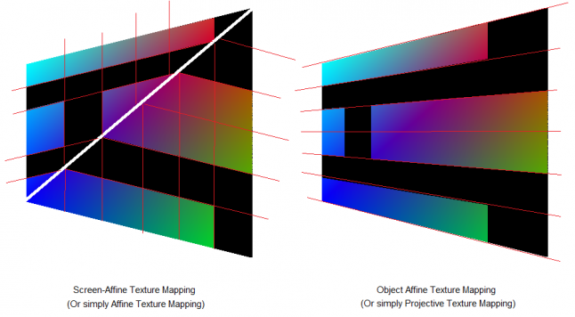 On the left we see that all parallel lines are still parallel, even after applying the Transformation to each individual Triangle. At least from our Point of view, which makes no sense when thinking about perspective. And on the right, we see that all parallel lines are still parallel when looking from the point of view of the Object. From our Screen Point of view, it looks perspective correct (and not parallel)
So, again, how do we then solve our Problem? Well, this is a bit tricky. We must first get into Object Affine Space. There, we can correctly interpolate our u,v-coordinates, from the point of view of the Object. After that, we must move back into Screen Affine Space, where we will be able to determine, where the Pixel will be placed, from the point of view of the Screen.
That's quite some esoteric mumbo jumbo I've just written. We can translate this into "plain" english:
Store the value (1/z) in the Vertex component w. (in Vertex Shader)
Multiply u and v by the value stored in w. (in or after Vertex Shader) -> Moving to Object Affine Space
Interpolate u,v,w using our usual Barycentric Coordinates. (before Pixel Shader)
Divide u and v by the value stored in w (before Pixel Shader) -> Back to Screen Affine Space
Done! Textures look good again. Phew.
Back to our actual Problem!
Dealing with number 2 ("The Pixel we are currently shading might actually cover larger portion of a texture") is quite a bit more involved. Again, let's use an example. Take a textured Triangle that is far away from the Viewer. This Triangle would appear very small. How do we take into account, that the Pixel we are rendering covers multiple Texels? (Don't be alarmed by the Affine look of this picture - I'm just bad at drawing)
If we won't do anything about this, we would have to decide between one of those Texels and we will end up with an effect known as Texture Aliasing. It's not pretty. (Picture taken from GPU Gems Chapter 25, (a) Texture Aliasing, (b) "Anti-Aliasing")
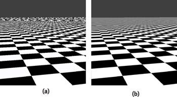
A possible solution is rather simple, Sample the Texture at multiple points within a single Pixel and take the mean color value of the Texels. This will give an effect similar / same as (b) - known as Super sampling.
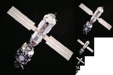
Super sampling is quite expensive. Instead, the common solution to this problem is something called Mip-Mapping. The idea is the same as Super sampling, with the difference, that we pre-compute how the super sampled Texture might look. Interestingly enough, well done Mip-Mapping often looks as good, if not better, than Super sampling - at least for Textures.
Say, we have a 512 x 512 Texture. We simply add a lower level of detail to memory, size 256 x 256, where each Texel is the mean value of a 2 x 2 Grid (or some other combination) on the original Texture. This lower level detail artificially creates the blending of Texels when we get further from the textured Triangle. Now when Rendering, we sample either use the Full texture for close z-values or the lower level of detail Texture for larger z-values.
We continue this, by adding even lower detail levels. 128 x 128, 64 x 64,... The resulting Texture might then look like this (Taken from Wikipedia):
Obviously, Mip-Mapping costs more Memory and we have to keep in mind to adjust the u,v-coordinates. But, we save on Memory Access later on compared to full on Super sampling - increasing speed!
What Mip-Map level is used is determined by the size and distance of the Triangle from the Camera. We have discrete steps between our levels, 32 x 32 -> 64 x 64. So, we somehow have to determine what level of detail we use.
Or, we can even interpolate between them. Interpolating between Mip-Maps is often done via a technique known as Trilinear Filtering (Bilinear Filtering in u,v-direction, as well as linear filtering between Mip-Maps). Cool.
Now, you've heard a lot of the typical Texture buzz-words: Trilinear Filtering, Mip-Maps, Aliasing... What about Anisotropic Filtering?
Well, Anisotropic Filtering is a type of Mip-Mapping that also takes into account the tilting / squishing of our Textured Triangle. In addition to our normal Mip-Map, we therefore also store squished versions of each Mip-Map level. (Image taken from Wikipedia as well)
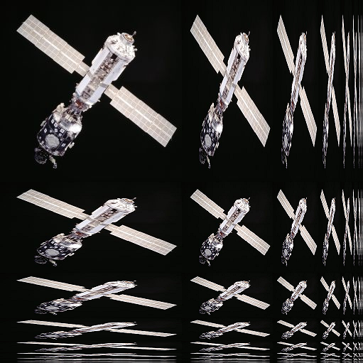
This obviously further increases Memory usage. But hey, it does greatly improve visual quality.
So, what did we use in our sGL? Point Sampling. We used Point Sampling. Let's just pretend it's because we like the Style and not due to our laziness.
Lighting
After we have Textured our Triangle, what about Lighting? Well, in the age of Shaders, we are left with two feasible methods of Lighting. Per-Vertex and Per-Pixel Lighting. It should be pretty obvious from the naming, where each of them take place. Let's take a brief look at both. (We ignore things like Lightmaps for now)
In the past, Lighting was only sensible to be done / calculated per-Vertex. The result was then interpolated across the Triangle as we have discussed earlier. This used to be a fixed part in many Graphics Libraries and was sometimes done in the T&L unit of your Graphics Card, if you had one. But we don't want to dwell on the past.
What is interesting to point out is, that OpenGL, due to it's backwards compatibility still supports these old functionalities (glLightfv() and such). I highly recommend you completely ignore these old fixed pipeline functions, if you can.
Nowadays (in both per-Vertex as well as per-Pixel) Lights are defined as user created structures, passed to the Shader and calculated "by hand". This gives the user complete freedom over how they look and feel.
In per-Vertex Lighting, we can simply loop over a set amount of lights in the Vertex Shader and apply them to the Vertex color based on some Lighting formulas. As we interpolate the color over the entire Triangle later on, it gives the illusion of shading.
In per-Pixel lighting, the only difference is really, that we do all those calculations in the Pixel Shader.
The difference should be obvious: Speed. Per-Pixel lighting is very costly. So it makes sense, even today, to do per-Vertex shading wherever possible.
We will revisit Lighting (and Shadows!) in depth in a future Article.
Special Effects
Special Effects themselves are not as complicated as they may seem. The pure logic behind most Special Effects can be found with a bit of search on the Web. (A really nice, yet a bit old, resource are the GPU Gems and in general nVidia Research).
The real trick with Special Effects is Speed! For example, Global Illumination is itself quite simple to do. You can whip out a simple Shader that has Global Illumination with a bit of research and logical thinking. Though, it will probably run at 1 Frame every few minutes. If that. The real struggle comes from making it run in real-time - and suddenly you end up with Voxels when doing Global Illumination... But you know what? Even the logic behind that high-end technology isn't some well guarded secret and widely available (mostly thanks to academia).
What I'm trying to say, don't be afraid of how complicated Special Effects look in Games. Be afraid of the performance hit.
6. Drawing to the Backbuffer
We've finally got our Result from the Pixel Shader! It's the Pixels position (x,y), as well as it's z-coordinate and of course it's Color.
Time to do something with it. Well, obviously we want to draw it! But, we don't draw it directly to the Screen. That would look strange. The player would see random Triangles be drawn everywhere and sometimes over each other.
So, we draw the scene off-screen first in some big Buffer. Also known as the Backbuffer. Let's take a look at how we do this in our sGL:
void sGLSetPixel(int x, int y, float z, color_t color)
{
	// We check if we are actually setting the Pixel inside the Backbuffer
	if (x >= 0 && x < g_sGLBackbufferWidth)
	{
		if (y >= 0 && y < g_sGLBackbufferHeight)
		{
			int screenIdx = y * g_sGLBackbufferWidth + x;

			g_sGLBackBuffer[screenIdx] = color;
		}
	}
}
Nothing special going on here.
But! Keep in mind, we are overwriting anything that was at that exact spot in the Backbuffer. This means, if we had a Triangle at that point, it get's overdrawn. And it wouldn't even matter if the present Triangle is in front or behind the other Triangle logically.
So we need to check which one is in front. But how? Well, we still have the z-coordinate, we can use that!
Depth Checking
But this means, we need to store the z-Coordinate of the Pixel that has been drawn at that exact spot earlier. We therefore need another Buffer just storing the z-coordinates! Let's call it the Depth Buffer. Usually, at this stage, the z-coordinate we use for Depth Testing has been intentionally "distorted" through the Perspective Transformation. The Z-Coordinate is thus not uniformly distributed, but rather takes the form of 1 / z. For us at this point, it suffices to know, that they usually range from -1.0 -> 1.0 or 0.0 -> 1.0.
Our simple check inside the sGLSetPixel() function might look like this:
// We check if we violate the Depth Buffer
if (z > 0 && z <= g_sGLDepthBuffer[screenIdx])
{
	g_sGLBackBuffer[screenIdx] = color;
	g_sGLDepthBuffer[screenIdx] = z;
}
Again, pretty straight forward. But this only makes sense, if the Depth Buffer had a large value to begin with. We thus have to keep in mind to clear the Depth Buffer to some "larger" value, in this case, 1.0. OpenGL also allows you to invert the z-depth check from "less than" to "greater than".
OpenGL | Description | sGL |
|---|---|---|
glEnable(GL_DEPTH_TEST) | Enables Depth Testing | sGLEnableDepthTest() |
glDepthFunc() | Sets the type of Depth Test (less than, greater than, greater equal....) | Always "less equal" |
glClearDepth() | Clears the Depth Buffer to the specified Value | sGLClearDepth() |
Alpha Blending
Depth testing isn't the only thing we need to do at this stage. Another thing we need to think about is Alpha Blending. What if we draw semi-transparent Triangles? Well, let's just blend those Triangles with the values that are already present in the Backbuffer.
// We check if we violate the Depth Buffer
if (z > 0 && z <= g_sGLDepthBuffer[screenIdx])
{
	if (g_sGLAlphaTest == true)
	{
		color_t cCol = g_sGLBackBuffer[screenIdx];

		cCol.r = cCol.r * (1 - color.a) + color.r * color.a;
		cCol.g = cCol.g * (1 - color.a) + color.g * color.a;
		cCol.b = cCol.b * (1 - color.a) + color.b * color.a;

		g_sGLBackBuffer[screenIdx] = cCol;
	}
	else
	{
		g_sGLBackBuffer[screenIdx] = color;
	}
	g_sGLDepthBuffer[screenIdx] = z;
}
We first check if Alpha Blending is enabled. Then we gather the present Color inside the Backbuffer and mash that together with the new Color in respect to the Alpha value. Finally we draw the new Color. Done.
Before we look at some Problems with this, here are the Functions:
OpenGL | Description | sGL |
|---|---|---|
glEnable(GL_BLEND) | Enables the Alpha Testing | sGLEnableAlphaTest() |
glBlendFunc() | Determines how the Alpha Value is treated (i.e. which gets multiplied by Alpha and which by 1 - Alpha) | Hard Coded as above |
Easy.
Or so it seems. Alpha Blending is a pain! Did you notice that things will only blend, when the Color is already present in the Backbuffer? This is a problem. Our Z-Buffer won't save us here.
Okay fine, we can rectify this problem by first drawing everything that is non-transparent and follow that by everything that is transparent by hand. Easy right?
Nope... What if we want to draw two transparent Triangles on top of each other?
We have to sort. Yes, even with a Z-Buffer, we still need to sort our transparent Triangles by their z-Value by hand before we do the draw call.
And we will notice another Problem...
Notice how the seam between the two Triangles overlap and then gets blended? This is a problem / feature of how we do our Scan Line Algorithm. We've used a conservative Algorithm for our Fill.
Polygon Fill Methods
This probably should have been in the Scan Line Section, but here we can actually see its effects: It matters strongly how we decide which of the "Triangle-Edge-Pixels" we fill and which we don't.
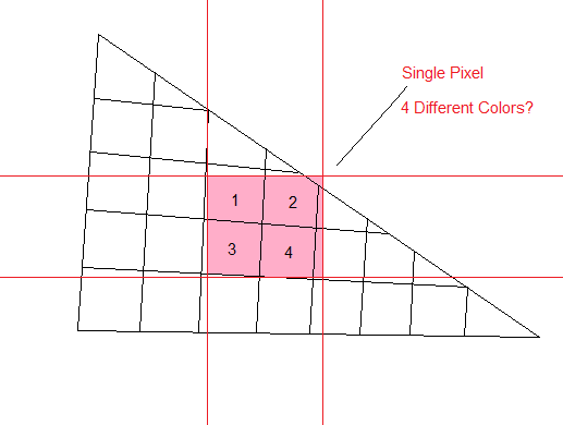
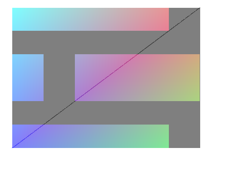
Basically we can decide to be standard or conservative when deciding what Pixels to fill. The difference is simple. Conservative filling means, we fill each Pixel that is touched by the Triangle, no matter by how much. In Standard fill mode, we only fill Pixels, if their center is covered by that Triangle. Let's clarify this with a Picture:
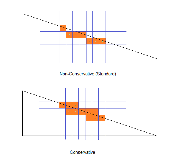
As we are using conservative filling in our Scan-Line method, we will have overlap on each of the Triangles Pixels that share an edge with another Triangle (as in the example further above). For the standard fill mode, this wouldn't have happened, as when the two Triangles share an edge, only one of them occupies the Pixel's center.
This means, Alpha Blending looks best in Standard fill mode. This has also lead to the fact that conservative filling isn't even supported in most Graphics Libraries! Only now is DirectX (and Vulkan?) adding this feature to switch between the modes.
But why would we even want it?
Well, imagine a Triangle so small, it doesn't even cover a single Pixel's center. In Standard fill mode, it would be invisible!
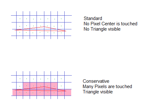
This is also a reason why line rendering using Polygons is actually quite tricky. If the line gets too thin, many Pixels disappear -> no line!
Buffers, Buffers, Buffers
So far we have been drawing everything to the Backbuffer. The Backbuffer is mostly a predefined Area on your Graphics Card Memory. Can we draw to some other Buffer instead? Sure we can. The Backbuffer is pretty much like a Screen-sized Texture anyway, so let's just draw to another Framebuffer.
And we often will do this for Special Effects, Shadows... But more on that some other time!
7. Swapping Back and Frontbuffer
And Swap. Our Scene is on the Screen!
Done!
Let's stop here for now. We could go into far more detail on each subject presented here, and we most likely will. My main goal was to give a little overview of what happens under the hood. This knowledge will help us later on when we do more advanced stuff.
The Focus has been mainly the Software side of things. We will be diving deeper into the Hardware side soon!(-ish)
As for our little sGL, it's best you forget about it after reading this. It's sole purpose was to give a little example of how things might work - Don't write your own Graphics Library for your game if you can avoid it. If you are still interested though, check out the Mesa project.
I hope this Article has been interesting, even if you have some familiarity with OpenGL or Graphics Programming in general.
Feel free to contact me via Twitter @Spellwrath or leave a comment below, if you have any questions.
Read more about:
Featured BlogsAbout the Author(s)
You May Also Like


.jpeg?width=700&auto=webp&quality=80&disable=upscale)