Daily news, dev blogs, and stories from Game Developer straight to your inbox
Sponsored By
Water interaction model for boats in video games: Part 2
Avalanche Studios senior software engineer Jacques Kerner is back with more of the deep physics work behind Just Cause 3's advanced boat simulations.
26 Min Read

Jacques Kerner is a senior software engineer at Avalanche Studios. In this article, he discusses the work put into Just Cause 3's boat physics.
Welcome to part 2 of the series on boat physics for video games. In part 1, I explained the principles of buoyancy and how we chose to calculate the hydrostatic forces acting on a boat. I also stated that we were laying an important foundation for calculating not only the hydrostatic forces but also the hydrodynamic forces of our simplified model. By this I meant that we will compute additional forces on each submerged triangle, sum them up, and apply them to the boat. It's that simple.
Or so one could think at first. It turned out that modeling the rest of the forces to give the boat an acceptable dynamic response took much more research and iteration than laying all the foundation presented in part 1 and computing the buoyancy. Retrospectively, in comparison, the first part was a walk in the park. That second part felt like running an obstacle course in a foggy jungle full of spear pits, while pursued by angry wolves (a.k.a. producers).
If you haven't read part 1, here's a quick summary. The boat is modeled as a triangulated mesh. We approximate the surface of the water with a height field, and, using a fast approximate triangle vs height field intersection algorithm, we determine the part of the boat lying below the water, as a list of fully submerged triangles. Each triangle of the original mesh can produce 0, 1, or 2 fully submerged triangles. You can see the algorithm at work in figure 1.
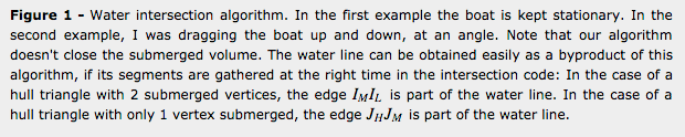
Figure 2 illustrates the typical hydrostatic pressure distribution over the submerged part of the boat. The coarse approximation is that we consider the pressure constant over a submerged triangle. The motion of the boat shown here is not the result of hydrostatic forces only.

Figure 2 - Hydrostatic pressure distribution obtained with our model. Note that this behavior was obtained with the full model, not by applying only hydrostatic forces to the boat. The boat is dropped from 2 meters high and given some time to settle. It is then teleported 2 meters under water and left to rise to the surface and settle again. The pressure is considered constant over an entire submerged triangle, which can be quite big. The bigger the hull triangles, the coarser the approximation. However the model works and is stable even with fairly low poly meshes. Good enough for army work!
As can be seen in figure 3, applying only the hydrostatic forces is not enough to accurately simulate a body in water. To me, this is what is great about programming and simulation. It gives us the ability to verify if a given model is close to describing a real physical phenomenon. While we are hopelessly slow at coming up with good models for physical phenomena, especially in accurate mathematical terms, our eyes and brain are astoundingly good and fast at detecting when a simulation doesn't capture their essence to a high order of precision. In this case, the simulation shows us how important resistive forces are for a boat, and what it would look like if these resistive forces didn't exist, in some kind of weird, very bouncy, parallel universe.
Figure 3 - Dynamic response of a boat subjected to hydrostatic forces only, on perfectly flat water. It would get pretty messy in there with a fishing line. It's clear that resistance forces play a big role in reality.
In figure 3, it looks like the boat is mounted on a spring rather than floating in water. We know from experience that a boat dropped from a height, would very quickly stop bouncing up and down. This is called damping, the attenuation of motion by forces opposing it. As a result, the maximum height reached by consecutive peaks in an up and down motion gets smaller and smaller. In the case of critical damping, the forces are strong enough to prevent oscillations altogether.
Fun with JC3's light patrol boat. The water simulation is provided by NVIDIA WaveWorks.
Stabilizing the model
When I set out to develop a simple model of the forces acting on the boat, I only had a nebulous plan of what I wanted to achieve. It could be summed up as a mix between "developing a stable boat model that reacts to big waves in a realistic manner and is fun to drive" and "seriously, how hard can it be". While we figured out the forces to apply to the boat, we needed to stabilize it so it wouldn't bounce uncontrollably. Also, if we introduced forces which were too big or unstable, we needed a safety net to prevent the boat from reaching insane speeds. So the first thing we did was to add some strong damping forces, both for the linear and angular components, to stabilize the oscillation I just mentioned. The damping is simply proportional to how much the floating body is submerged in water. As you may recall, at every frame, we determine a list of submerged triangles, so a simplistic measure of how much the boat is submerged is given by the ratio between the submerged area and the total surface area of the boat.
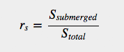
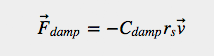
We can introduce a linear damping force looking like this for instance:
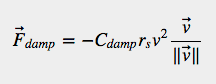
or a quadratic damping:
Before we dive in: a spoiler
In the end, we used 3 different forces coming from the interaction between the boat and water: viscous water resistance, pressure drag, and slamming force (or water entry force). Each of these forces was added to the model because they somewhat correspond to a reality, and also because they address a certain problem. In the rest of the article, I explain which physical reality each of these forces is meant to represent, and I also explain what motivated us to include the force, i.e. which specific set of problems the force addresses. Remember that this is a simplified model, so some of the forces are only vaguely related to a physical reality. This is especially the case of the pressure drag, which is a gross simplification of what is referred to as wave resistance and spray resistance, in more advanced hydrodynamic theory. A fourth force, the added mass force, didn't make it in the model in the end, but I still wonder how it could be factored in to give a better sense of inertia.
The drag equation
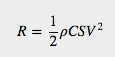
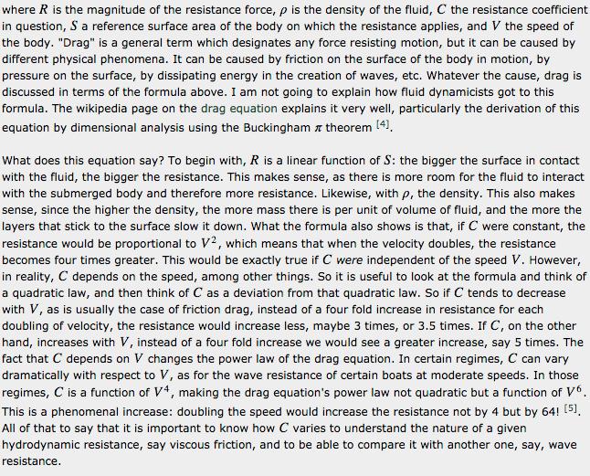
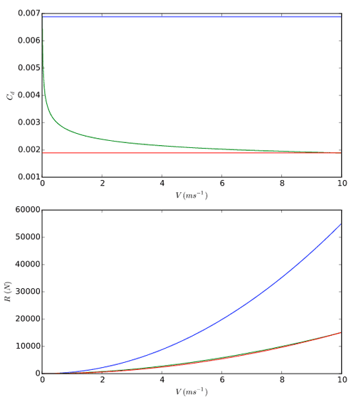
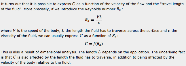
Since a lot of the discussion ahead of us is about drag, I want to pause for a second and look at the drag equation. If you are familiar with it you can skip ahead to the next section. In fluid dynamics, the tradition is to express drag in the form:
Ingredients of the triangle
Before I start describing our model of hydrodynamic forces, I introduce a few quantities and vectors related to the submerged triangles of the boat hull. All forces are computed using these.
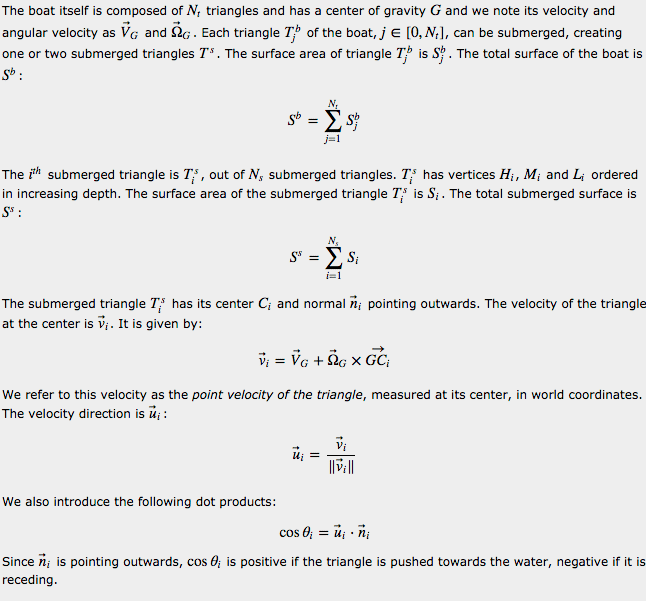
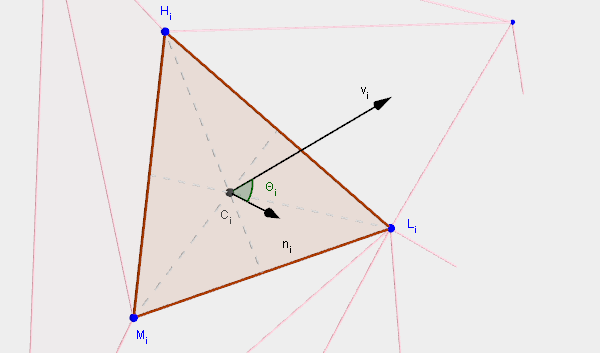
Figure 5 - Some useful quantities on each submerged triangle
Viscous Water Resistance
As in many texts on hydrodynamics, I will start with viscous water resistance. Viscous resistance occurs when water flows across a surface. Because there is strong interaction between the water immediately next to the hull and the surface of the hull, there is a microscopic layer of water that essentially "sticks" to the surface, and moves with the boat. Then as the distance increases away from the hull, the water sticks less and less. To simplify a little bit, each microscopic layer of water at a given distance from the surface interacts with - "sticks to" - the one immediately before it and the one immediately after. The intensity of that interaction is called viscosity. The more viscous a fluid, the more of it will stick to a surface and be dragged along with it. (*). This creates a force called viscous water resistance.
A lot of experiments have been conducted to measure viscous water resistance and there are good empirical formulas for predicting how much viscous water resistance a boat will generate. Let's take the example of a smooth flat plate dragged under water. If the plate is thin and dragged along its length so it doesn't face the flow, the force measured is pretty much all due to viscous water resistance. Many countries have built special facilities, commonly known as towing tanks, to measure, among other things, the hydrodynamic forces acting on submerged bodies, dragged in water. Some of the countries discuss the data collected as part of the International Towing Tank Conference, every 3 years since 1933 (with a 9 year hiatus due to World War II). In 1957 the ITTC agreed that the formula:
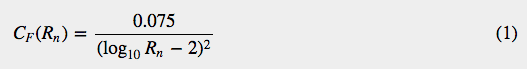
was a very good approximation of the data collected. This formula is called the ITTC 1957 model-ship correlation line, and it was not deduced analytically from first principles but is rather a regression function that fits the data closely enough for practical purposes. Strictly speaking, this doesn't make much difference to us: we just need a formula of some kind that we can apply on each of our triangles to calculate viscous friction. But it does show that the physics at play in fluid dynamics is complex enough that practicians resort to measured resistance as opposed to analytical formulas.
The viscosity of the fluid is not the only parameter influencing how great the force is. For one, the roughness of the surface itself matters. A rougher surface will interact strongly with a thicker layer of water than a very smooth surface. Even more important is how turbulent the flow is around the surface. In the front of the boat, the flow is said to be laminar. It is orderly and the layers at increasing distances from the surface flow parallel to each other, albeit at different speeds since they influence each other's speed at the microscopic level due to viscosity (**). But the longer the fluid flows across a surface, the more turbulent it becomes and the more the layers start mixing with each other. When the different layers mix in a turbulent way, the amount of fluid accelerated by the surface increases and gives rise to a stronger resistance. We should therefore expect more viscous friction resistance at the back of the boat than at the front. Finally, the 3D shape of the boat matters. It differs from a flat plate which changes the nature of the flow. Since the boat is not perfectly flat, the fluid needs to travel more distance and the relative velocity of the fluid is generally greater than the velocity of the boat. Due to the shape of the boat, the pressure changes across the surface, and this also impacts resistance.
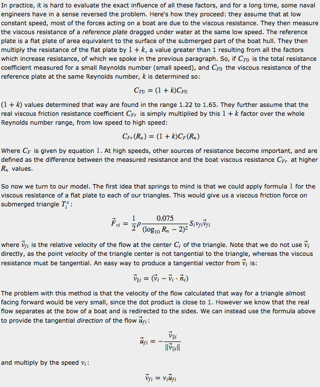
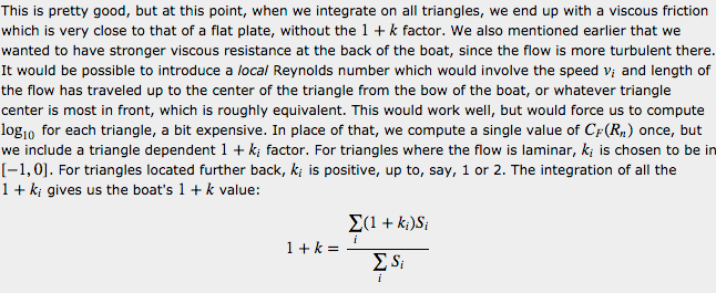
When a boat is sailing straight in calm water, the viscous resistance is the main force acting on the boat, especially. It is possible for the boat to be fairly out of the water, with very little surface opposing the motion, but with a lot of its bottom touching the water. In this case the pressure drag, which we discuss next, would be fairly small, but we would want a significant resistance from the water nevertheless. Additionally, if we were to make the boat 2 or 3 times longer without changing its facing area, we need the resistance to increase, and we get that with our viscous resistance, since it builds up mainly on the triangles of the hull tangential to the velocity.
Figure 6 - Dynamic behavior of a boat subjected only to the viscous water resistance in addition to buoyancy. Even though there are very good empirical formulas for the viscous water resistance and it is fairly easy to implement, it is nowhere near enough to dampen the boat's motion. Here the boat is dropped from about a meter high above the water. The viscous water resistance plays an important role, but is only significant at higher speeds.
Pressure Drag Forces
I now turn to a second force: the pressure drag force. This is also where we depart from any serious science but I will explain why I chose to do so.
In marine hydrodynamics, scientists distinguish wave pattern resistance, wave breaking resistance, added resistance in waves, spray resistance, eddy making forces, etc. These do not always correspond to a specific physical phenomenon. Rather, they are ways hydrodynamicists account for the fact that the total resistance on a boat moving in water exceeds the viscous resistance. By observing the boat and the water around it, it is clear that energy is dissipated other than by viscous resistance. The wave pattern resistance, for instance, can be evaluated by observing the waves created by the boat and deducing how much resistance must have been applied to the boat, by applying the Newtonian action reaction principle. But most of the time the slopes of the waves created in that fashion are supposed to be small. This simplifies the calculation and allows for a manageable formula to be produced. However this assumption is not correct, so the wave pattern resistance captures only a portion of the resistance. Near the boat, the slope of waves cannot be considered small and the waves break, giving rise to more resistance. This is called wave breaking resistance. Then depending on the model chosen for capturing the wave breaking resistance, it may be necessary to distinguish yet another resistance, the spray making resistance when the contact with water is so violent that the water becomes spray. While all this is fascinating, it is very complicated and it is too complicated for our model.
Instead of trying to capture different components by categorizing and evaluating them, an alternative would be to solve the Navier-Stokes equation numerically. However, as I have already said and cannot repeat enough, it is way beyond our scope in terms of performance and model complexity.
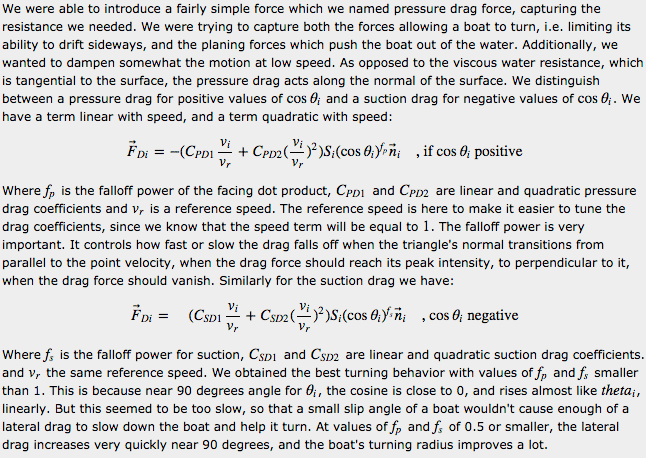
Figure 7 - Dynamic response with viscous resistance and pressure drag. The damping is now very good. But it's still not perfect. The dynamic response is not stiff enough and a residual oscillation remains. It would be possible to damp even more by selecting a higher value for the drag coefficient, but then the maneuverability of the boat is affected in an unrealistic way. For instance, the boat will slow down unrealistically fast from going at a given speed, it feels like the boat is in mud rather than water. We need yet another force, responsible for the very non linear or non quadratic dynamic response of a boat interacting with water.
The drag force is normal to the surface of the boat. It serves as a planing force at speed: provided the boat has enough propulsion to fight the force opposing its acceleration, the hydrodynamic pressure increases at the bottom of the boat, lifting it up. As the boat rises, less resistance is created by the friction and drag forces, except at the bottom of the boat. This is why planing boats tend to have flatter bottoms, so the horizontal surface they depend on for planing is not reduced by rising, unless they completely get out of the water.
Slamming Forces
With the viscous resistance and pressure drag resistance the boat model is starting to feel like a boat. However the boat can still penetrate water more than acceptable, and the overall response is lacking in stiffness. Instead of modifying the drag forces, which we wanted to fine tune for the turning behavior and planing forces, we decided to introduce yet another force which would mainly capture the violence of the response of the fluid to sudden accelerations or penetrations, which are almost like rigid collisions.
Very stiff collisions can be hard to model using a force depending on penetration depth or displacement when using a discrete integration scheme. An example of that is a very stiff spring. While the force is proportional to the displacement from a rest position, the higher the stiffness coefficient, the harder it is to simulate with a fixed time step. There are well known ways to deal with this problem but they tend to make the integration more complicated. Instead of going down that road, there is another option available to us, because it is easy to calculate the force required to completely stop the motion of the vehicle in one frame. Since it was important for this force to be arbitrarily stiff and the theory around slamming forces is very complex, we decided to shortcut the problem and proceed by starting from a perfectly stiff response and relax its stiffness as needed. We start by evaluating the intensity of the collision with water. If it is very violent, we can apply the motion stopping force entirely and the boat will stop as if it had hit the ground. On the other end of the spectrum, if the collision is of low intensity, we can let the other forces completely govern the motion and apply none of the motion stopping force. Then, in between the two extremes, we can blend using a variety of transition functions, more or less abrupt, for different dynamic results: linear, power functions, sigmoid, step.
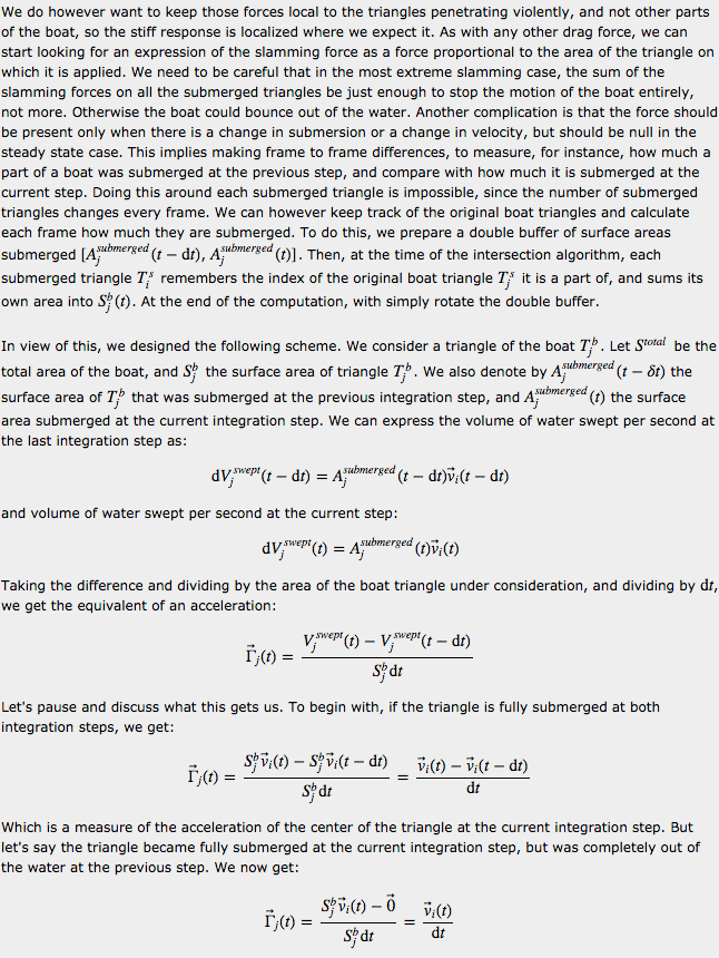
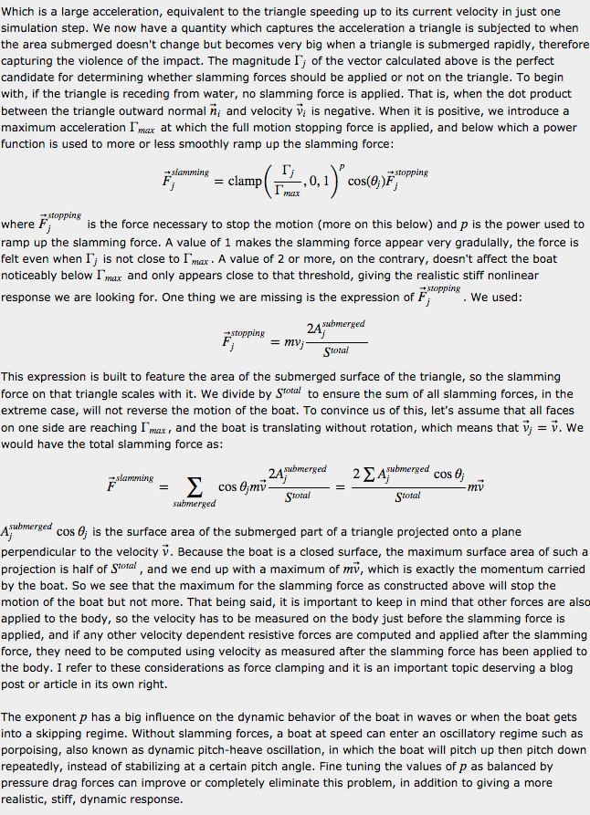
Figure 8 - Dynamic response with slamming forces of a boat dropped in water from a height of 2 meters
Figure 9 - Boat in moderate waves, accelerated to its cruising speed in a straight line. The propulsion used here is very simple, located in the rear, pushing slightly upwards. The stiffness of the response gets stronger at speed. A porpoising regime develops which can be avoided by a combination of finer tuning of the forces, a better designed hull, speed dependent trim of the propulsion, stabilizing aerodynamic forces. The bottom right view shows the distribution of drag forces on the hull.
Conclusion
The water interaction model we developed allows for a wide variety of boat sizes and shapes, from a 2 meter long jet ski to a 50 meter long corvette (see figure 10), or even bigger ships, in calm to very rough seas, without significantly changing the tuning variables for the forces. A brand new hull, of shape and dimension not tested before, can be dropped in water, with some propulsion, and be immediately in the ballpark of something usable. Of course, getting each boat to a shippable state required time placing and tuning the engine(s), rudders, trim tabs and other stabilizing fins, but a less procedural approach for the hydrostatics and hydrodynamics of the hull itself would have monopolized a lot more tuning time for a lesser result, which couldn't have coped as well with all the possible attitudes and velocities of the boat in water.
The relative simplicity of the model suited our needs. We are using Euler forward integration, the computation of the three forces is separate from each other and they are separately tunable, we can easily identify if a given force is pushing too much or too little in a given regime. Given more time, we would expand on the current model rather than choose a more realistic and computationally intensive model. But there are a few areas of improvements we would research, which I present below.
One such area is a force called the added mass force or virtual mass force, and I won't really do a better job at explaining it than by quoting wikipedia : "The origin of the [virtual mass] force is that the fluid will gain kinetic energy at the expense of the work done by an accelerating submerged body. (...). For ships, the added mass can easily reach 1/4 or 1/3 of the mass of the ship and therefore represents a significant inertia, in addition to frictional and wave making drag forces.". The virtual mass force is non existent when the boat velocity isn't changing. As a boat accelerates, it must displace and accelerate a certain proportion of fluid in front of it. As it decelerates, a certain proportion of the fluid around it has acquired kinetic energy that tends to be transfered back to the boat, opposing the deceleration. We would be reluctant to actually modify the mass of the vehicle itself to accomplish this effect. It can be confusing to reason with a vehicle which mass is changing, it would be much preferable to treat the virtual mass force like any other force so it can be compared to them and its effect measured on the maneuvering ability of the boat, like all the other forces. We made some attempts at implementing it but didn't get what we hoped for, but this could be because of a lack of time.
Another area of improvement would be to compare the forces of the present model to those acting on the hull as computed by a realistic computational fluid dynamics simulation (CFD). There are open source CFD packages such as OpenFOAM [6] which include ready made examples for simulating boat hulls in water. The Wigley hull benchmark is such an example. It features a hull which shape is entirely defined mathematically and which can be adapted by tuning a number of coefficients. This makes it easy to compare different simulations with each other or event to compare with towing tank data since the hulls can be made to match to a high degree of precision. Such an approach requires being able to run the CFD on the hull in well defined configurations of interest and to extract the force information for comparison. It also requires hours of computation on powerful machines for a few seconds worth of data. However, it could be well worth the investment to correct the areas where the forces of the simplified model diverge the most from those of the CFD computation.
Empirical formulas have also been developed by Savitsky in 1964 for prismatic planing hulls, that is, hulls which shape is very simple and well defined. Such formulas predict the "lift, drag, wetted area, center of pressure (...), as a function of speed, trim angle, dead rise angle and loading." These formulas could be used to adjust the forces in our model by testing on a similar hull in the simulation. [5]
Figure 10 - A wide variety of boats can be simulated with our model. The first boat in this video is a corvette, about 50 meters long. The second boat is a heavy patrol boat which hull shape is completely different and non conventional. Finally the last boat is a smaller multi hull, catamaran like speed boat, very flat. We have succesfully simulated boats as small as jetskis. The water simulation is provided by NVIDIA WaveWorks. [9]
Afterthoughts
When we set out to compute hydrodynamic forces, recall that we first added strong "fake" damping to stabilize the system. With that strong damping, the buoyancy was working great, with a floating barrel for instance. So I became triumphant a little too soon. When switching to the shape of a boat, we weren't getting "what we wanted" easily. Worse than that, we couldn't really agree on why what we were seeing didn't seem right. This happens when the objective hasn't been defined thoroughly enough. I now realize that we could have converged faster onto the final model by researching in more details how a boat behaves in water. For instance, what are the frequencies and amplitudes of motion of a boat at rest, slightly disturbed. How long does it take a boat to reach its top speed from a stop? How long does it take for a boat to "brake" nearly to a stop, from, say, its cruising speed. How much does a boat roll in a turn? How much does a boat trim (pitch its nose up) at speed? What is the typical slip angle of a boat when turning? How much speed does a boat lose in a turn if it started at top speed? All of these questions are complicated by the fact that there are a wide variety of boat shapes and sizes we wanted our model to cope with. While the mass of common land vehicles can vary by a factor 1,000 at least from a bike (~100 kg) to a humongous truck (100 tons), boats can vary from about the same minimum mass to 90,000 tons for an aircraft carrier, so by a factor 900,000. There are also very different shapes of boats, that significantly affect their behavior.
Once we asked ourselves those questions and gave an answer to them, even approximative, things moved at a much better pace. For instance, in [1] and [2], I gathered that typical planing boats will trim to a positive pitch of about 4 degrees, have a slip angle of around 20 degrees when turning hard and roll in at 25 degrees or more, inwards. These numbers were salutary because, for some reason, we had been trying to avoid too much slip angle, which led us to tune some of our constants much lower than they needed to be, and this was essentially putting us way off the map in the beginning.
It was fascinating to see that, as we added realistic forces to the model, we started encountering some of the same engineering problems boat designers encounter in the real world. I received a comment from a reader named Greg Sheel, on the first part of this series, saying: "A thought: if you implement a sufficiently realistic model for a boat on water, your in-game boat will have to be designed just like a real boat, to within some degree of accuracy, or it will have a terrible motion in the water". He couldn't have been more right and this brings up an interesting dilemma in vehicle physics simulation. The more realistic the simulation is, the more it will have to deal with realistic problems. It is great when the simulation starts exhibiting realistic traits and the players definitely perceive and appreciate it, but only if it doesn't get in the way of the game. An indication that we were on the right track was that the shape of the hull was having a big impact on the stability of the boat at rest. The dead rise angle, or the shape of the stern, particularly, change everything. But more realism may mean that a lot of development time is spent fixing problems brought on by a more realistic approach. In the case of the boat model, we noticed severe stability problems in certain regimes. We later learned that those problems were very real and known as porpoising, cork-screwing, chine walking, etc.
Thanks
I would like to thank my colleagues at Avalanche Studios: Hamish Young for his crucial insight and feedback, unrelenting optimism and enthusiasm while the model was developed and for his unequaled skills in tuning the boats and making them fun and exciting to drive; Roland Lesterlin for seeing the potential of the approach and believing this model could be completed in time; Chris Glover for bringing the boats to life by programming the special effects such as the Kelvin wake, which in itself would deserve an article, as well as water occlusion; the immensely talented Omar Shakir who produced and formatted the very sexy in-game captures, I still can't believe how good they look; and the rest of the team of Just Cause 3 for making such a fun, good looking game. I want to thank my Dad Richard for correcting the drafts for both parts of this series and for refreshing my memory on physics topics he already explained to me 25 years ago. Finally, a loving thank you to my wife Zoe for her patience and encouragements, and for letting me read books on hydrodynamics practically at the Christmas Eve dinner table.
Notes
(*) Different fluids have different viscosities. For instance, yogurt is very viscous. Something the Swedes don't seem to have noticed, since they still put yogurt in milk cartons. I discovered that on my first visit to Avalanche Studios in Stockholm. What you end up with is half the content sticking to the walls of the carton after you've tried pouring it out. Now you need to squeeze the content out like toothpaste. And you thought you had done well on your first grocery outing avoiding food in tubes!
(**) An amazing fact about laminar flow is that it is reversible (at the macroscopic level). A popular experiment to illustrate that consists of filling with transparent glucose syrup a cylindrical tank which outer wall can be rotated around its axis. The tank also has an inner cylindrical wall which remains fixed. If you insert 3 dots of corn syrup of different colors somewhere in the tank, and rotate the outer wallslowly to ensure laminar flow, the 3 colored dots will start spreading in a circle around the axis of rotation and look like they mix. But if you then rotate the outer wall in the opposite direction, you can return back to the original state with the 3 dots practically unchanged, exactly where they were in the beginning. Reversibility of laminar flow demonstrated at the university of New Mexico.
References
Hydrodynamics of High-Speed Marine Vehicles. Odd M. Faltinsen
Stability of a planing craft in turning motion. Y. Ikeda, H. Okumura and T. Katamaya
Principles of Yacht Design. Lars Larsson, Rolf E. Eliasson and Michal Orych
Hydrodynamic Design of Planing Hulls, Marine Technology, D. Savitsky
Procedures for Hydrodynamic Evaluation of Planing Hulls in Smooth and Rough Water, D. Savitsky, P. W. Brown
About the Author(s)
You May Also Like


.jpeg?width=700&auto=webp&quality=80&disable=upscale)