Daily news, dev blogs, and stories from Game Developer straight to your inbox
Sponsored By
Featured Blog | This community-written post highlights the best of what the game industry has to offer. Read more like it on the Game Developer Blogs or learn how to Submit Your Own Blog Post
Shader tutorial: CRT emulation
Writing a shader that emulates CRT. Using Unity and explaining the shader principles.
7 Min Read

In this article I want to tell you about creating a shader to emulate CRT effect in your game. I will be making this on Unity using CG shader language, but I think there is no problem converting it to HLSL / GLSL or whatever. Also, I will write the following text for those who don’t even know what the shaders are and how to start.
But first of all I want to warn you that using such effect are not always good for your game. Don’t try to use such shaders everywhere. For example, our game (VHS Story) has lots of references to 80-90s and we want to make some cutscenes where our hero watches the TV. So, we’re planning to use this shader for such cutscenes, but not for general gameplay picture.
So, let’s go!
What are the shaders and how do they work?
Shader - is a small sub-program that runs on a GPU and is being called for every vertex (“vertex shader”) or every texture pixel (“fragmental shader”). In general even a drawing a textured triangle needs a shader.
In this article I will talk about pixel (fragmetnal) shaders because we don’t need to transform a triangle coordinates for our task.
The other great thing about shaders you should know is that they can run in a parallel. Drawing one pixel with a shader doesn’t rely on the result of other pixels draw. So, every shader has only texture coordinates and a texture itself in the input and puts the color of the result pixel in the output.
There are different shader languages supported in Unity, but I recommend to use a CG language because it will run on both - OpenGL and DirectX. So, we don’t need to write two shaders for each of these graphical APIs.
Let’s start!
We’re writing a camera post-effect (need to mention - you'll need a Unity Pro for that). So, the 1st thing we should do is to write a shader that processes the whole camera image.
Let’s create a simple shader that doesn’t do anything (create a file with the “.shader” extension):
[Source code available here]
Let’s talk about something we have here:
Properties - describes the shader input parameters. Here we have a texture only.
vert - is a vertex shader and frag is a fragmental (pixel) shader
struct v2f - describes a data structure being transferred from a vertex shader to the fragmental shader
block with uniform keywords - create links to the external parameters described in a “properties” section
In this example the vertex shader makes some vertex matrix magic we will not dig in. That just works and we don’t need to modify it unless we want to make some geometry (vertex) transformations.
The fragmental shader gets coordinates from the vertex shader, reads the texture at these coords and outputs the “color” variable.
Shader language uses multi-component data types. To describe an array of 2 floats you can use “float2” etc. And you can address a single component of this variable using .x .y .z .w (or .r .g .b .a which are equivalent). I.e. “myvar.y” is equivalent to “myvar.g”.
Now let’s apply this shader to the camera. Here is a controlling C# script:
[code]
Now let’s add this script to the main camera and drag our shader in the “shader” field of the script.
Running the game you shouldn’t notice any changes. That is because our shader doesn’t do anything. The easiest way to test it is to add something like “color.r = 0;” in it. This will result an output picture without a red component.
Let’s start implementing our effect.
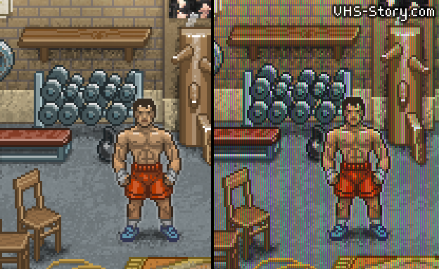
First of all we will try to make a picture look like it is made of big lines of RGB pixels:
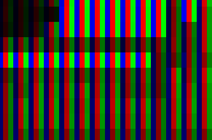
That’s quite simple. All you need to do is to leave only B component for every 1th column, only R for the every 2nd and G for the 3rd.
But now we have a task to get screen coordinates in our pixel shader. That can be done by some calculations in a vertex shader and transferring this result to the pixel one.
First of all let’s add one field to our v2f struct:
float4 scr_pos : TEXCOORD1;
and add this line to the vertex shader:
o.scr_pos = ComputeScreenPos(o.pos);
After this we will get a screen coordinate in the pixel shader which will be in the 0...1 range. But we want real pixels. That can be easily done:
float2 ps = i.scr_pos.xy *_ScreenParams.xy / i.scr_pos.w;
Now we have a pixel screen coordinates in the “ps” variable. Everything is quite simple now:
int pp = (int)ps.x % 3;
float4 outcolor = float4(0, 0, 0, 1);
if (pp == 1) outcolor.r = color.r;
else if (pp == 2) outcolor.g = color.g;
else outcolor.b = color.b;
return outcolor;
We will get something like this:
You can see two moments now. First is that our effect is too strong. And second is that our picture became dark. Let’s fix that.
The easiest way is to leave some of R/G color in the “B” column, etc. That can be done by multiplying the input color by some mask. For example, the mask should look like (1, k1, k2, 1) for the “R” column, (k2, 1, k1, 1) for the “G” and (k1, k2, 1, 1) for the “B” one.
Let’s add these coefficients to the properties section:
_VertsColor("Verts fill color", Float) = 0
_VertsColor2("Verts fill color 2", Float) = 0
and create links:
uniform float _VertsColor;
uniform float _VertsColor2;
Then let’s make the needed math in the pixel shader:
if (pp == 1) { muls.r = 1; muls.g = _VertsColor2; }
else if (pp == 2) { muls.g = 1; muls.b = _VertsColor2; }
else { muls.b = 1; muls.r = _VertsColor2; } color = color * muls;
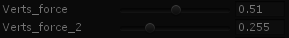
The last thing we need is to make these parameters controllable from the Unity. Add these lines in your C# script:
[Range(0, 1)] public float verts_force = 0.0f;
[Range(0, 1)] public float verts_force_2 = 0.0f;
And add this in the OnRenderImage method, just before the Graphics.Blit call:
mat.SetFloat("_VertsColor", 1-verts_force);
mat.SetFloat("_VertsColor2", 1-verts_force_2);
I’m making “1-verts_force” to make parameters more human-understandable. The larger the parameter is - the stronger the effect.
If everything is done correctly you should see the following fields in the camera inspector:
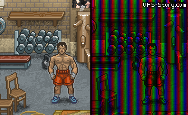
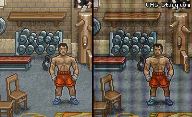
And now let’s look at the result:
That’s better, but let’s add more brightness and some contrast to the picture.
Shader:
_Contrast("Contrast", Float) = 0
_Br("Brightness", Float) = 0
....
uniform float _Contrast;
uniform float _Br;
....
color += (_Br / 255);
color = color - _Contrast * (color - 1.0) * color *(color - 0.5);
C#:
[Range(-3, 20)] public float contrast = 0.0f;
[Range(-200, 200)] public float brightness = 0.0f;
...
mat.SetFloat("_Contrast", contrast);
mat.SetFloat("_Br", brightness);
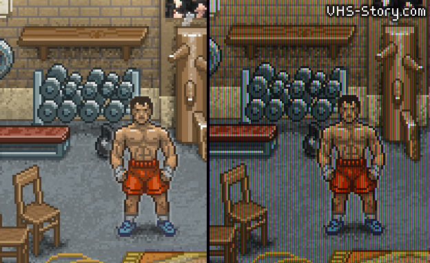
Result:
(contrast = 2.1, brightness = 27)
So, let’s add scanlines now. That’s very simple. We should darken every 3rd line.
if ((int)ps.y % 3 == 0) muls *= float4(_ScansColor, _ScansColor, _ScansColor, 1);
And last thing will be adding some boom. You can download a bloom shader here:
Done!
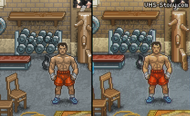
Of course, this shader will look best on the x3 pixel graphics, like my examples have.
PS: Also you can achieve this effect just by multiplying one texture by another. That will be faster. But the aim of this article was not to write an optimal shader, the aim was to show you how it is done.
Read more about:
Featured BlogsAbout the Author(s)
You May Also Like


.jpeg?width=700&auto=webp&quality=80&disable=upscale)