Daily news, dev blogs, and stories from Game Developer straight to your inbox
Sponsored By
Featured Blog | This community-written post highlights the best of what the game industry has to offer. Read more like it on the Game Developer Blogs.
Making 2D portals using shaders
Step by step walk through the process of creating a simple 2D portal shader.
14 Min Read

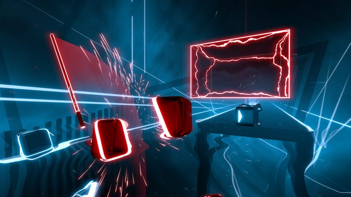
This post will explore how to achieve an effect like this:

My game started off as a ludum dare game for LD30 - Connected Worlds. It featured a single mechanic - each of the two main characters could make a noise (ping) in the identical connected world on the other side of the screen. About half of the people playing the game had a hard time grasping the concept easily, so I changed it around a bit.
I made the ping so that it works in your current world, unless you're inside a portal (in which case it will manifest in the alternate world). I tried a few implementations of the portal, including swapping the characters over to the other world but that was jarring and confusing.
I thought a lot about how to implement this, but because there were simply too many moving pieces, doing it on an item by item basis would have been extremely difficult. This brought me to a shader-based solution to this problem.
Conceptually the following shader works as a camera post-effect, just like the blur or vignette unity built-in filters work. It receives an input image (well, RenderTexture) and has an output one with the result of the operation.
1. Shader and post-effect setup
Let start with the least useful post-effect just to prove this set-up works. Create a Camera with mostly default settings:

The most important changes are Clear Flags (so it doesn't clear the screen), make it ortographic and set its depth above the other camera(s) from your project (so it gets rendered after them). Then create a new script (PortalEffect.cs) with this initial code:
using UnityEngine;
using UnityStandardAssets.ImageEffects;[ExecuteInEditMode]
[RequireComponent(typeof (Camera))]
public class PortalEffect : PostEffectsBase
{
private Material portalMaterial;
public Shader PortalShader = null;public override bool CheckResources()
{
CheckSupport(false);portalMaterial = CheckShaderAndCreateMaterial(PortalShader, portalMaterial);
if (!isSupported)
ReportAutoDisable();
return isSupported;
}
public void OnDisable()
{
if (portalMaterial)
DestroyImmediate(portalMaterial);
}public void OnRenderImage(RenderTexture source, RenderTexture destination)
{
if (!CheckResources() || portalMaterial == null)
{
Graphics.Blit(source, destination);
return;
}
Graphics.Blit(source, destination, portalMaterial);
}
}
Now create a new shader, PortalShader.shader with the following code:
Shader "VividHelix/PortalShader" {
Properties {
_MainTex ("Base (RGB)", 2D) = "white" {}
}
SubShader {
Pass {
CGPROGRAM
#pragma vertex vert
#pragma fragment frag#include "UnityCG.cginc"
uniform sampler2D _MainTex;
struct vertOut {
float4 pos:SV_POSITION;
};vertOut vert(appdata_base v) {
vertOut o;
o.pos = mul (UNITY_MATRIX_MVP, v.vertex);
return o;
}fixed4 frag(vertOut i) : SV_Target {
return fixed4(.5,.5,.5,.1);
}
ENDCG
}
}
}
After you create the shader, don't forget to set it in the PortalShader property of the PortalEffect script.
Here's a screenshot from before the effect is active:

After activating the effect you should see this:

The grey is caused by the line fixed4(.5,.5,.5,.1) - it's a gray with 50% red, green, blue and an alpha of 1.
2. Adding UV coordinates
Let's bring in the UV coordinates. These range from 0 to 1. It's useful to think of this post processing effect as operating on a single screen wide quad with a texture of what the previous cameras rendered.
This new code:
struct vertOut {
float4 pos:SV_POSITION;
float4 uv:TEXCOORD0;
};vertOut vert(appdata_base v) {
vertOut o;
o.pos = mul (UNITY_MATRIX_MVP, v.vertex);
o.uv = v.texcoord;
return o;
}fixed4 frag(vertOut i) : SV_Target {
return tex2D(_MainTex, 1-i.uv);
}
Will create a double-flip, flipping the image both vertically and horizontally (equivalent to a 180-degree rotation):

Not exactly useful, the magic happens in the 1-i.uv part. Replacing that with just i.uv will result in this effect becoming an "identity" effect, where it doesn't really perform any changes on the source image. Doing something like return tex2D(_MainTex, float2(1-i.uv.x,i.uv.y)); will do just a horizontal (left vs right) flip:

3. Pasting another area
We can modify the shader a bit to copy over a different area of the screen by messing with the UV values:
fixed4 frag(vertOut i) : SV_Target {
float2 newUV = float2(i.uv.x, i.uv.y);
if (i.uv.x < .25){
newUV.x = newUV.x + .5;
}
return tex2D(_MainTex, newUV);
}

Notice how the left quarter of the screen is overwritten. Playing with the .25 value to affect how much of the left side will be overwritten. The .5 we're adding make the x jump from 0-0.25 to 0.5-0.75 which is on the opposite side of the screen.
4. Pasting a circular area
Let's introduce a distance function to paste a circular area:
if (distance(i.uv.xy, float2(.25,.75)) < .1){
newUV.x = newUV.x + .5;
}

Hmm, that ellipse could be a bit more circular. The problem here is caused by the width and height of the screen not being equal (we're effectively computing distances between 0-1 ranges). Measuring it, this ellipse's diameter height will be 20% of the screen height and its width will be 20% of the screen's width (since we're checking the radius against .1 or 10%).
5. Pasting a circuler area revisited
To fix this problem, we need to consider the screen width and height in our distance call:
fixed4 frag(vertOut i) : SV_Target {
float2 scrPos = float2(i.uv.x * _ScreenParams.x, i.uv.y * _ScreenParams.y);
if (distance(scrPos, float2(.25 * _ScreenParams.x,.75 * _ScreenParams.y)) < 50){
scrPos.x = scrPos.x + _ScreenParams.x/2;
}
return tex2D(_MainTex, float2(scrPos.x/_ScreenParams.x, scrPos.y/_ScreenParams.y));
}

6. Swapping areas
Swapping is now equivalent to performing a double swap, from one location to the other:
if (distance(scrPos, float2(.25 * _ScreenParams.x,.75 * _ScreenParams.y)) < 50){
scrPos.x = scrPos.x + _ScreenParams.x/2;
}else if (distance(scrPos, float2(.75 * _ScreenParams.x,.75 * _ScreenParams.y)) < 50){
scrPos.x = scrPos.x - _ScreenParams.x/2;
}
Getting there:

7. Introducing edge fading
The transition looks rather abrupt so we can introduce a bit of fading. We can use a lerp function for that.
Starting simple:
float lerpFactor=0;
if (distance(scrPos, float2(.25 * _ScreenParams.x,.75 * _ScreenParams.y)) < 50){
scrPos.x = scrPos.x + _ScreenParams.x/2;
lerpFactor = .8;
}else if (distance(scrPos, float2(.75 * _ScreenParams.x,.75 * _ScreenParams.y)) < 50){
scrPos.x = scrPos.x - _ScreenParams.x/2;
lerpFactor = .8;
}
return lerp(tex2D(_MainTex, i.uv), tex2D(_MainTex, float2(scrPos.x/_ScreenParams.x, scrPos.y/_ScreenParams.y)), lerpFactor);
This code will fade between the source and destination areas, using 80% (corresponding to the .8) of the newly swapped pixels:

Now let's make this fading a bit more gradual by using a distance function (and focusing on a single paste operation rather than the full swap for simplicity):
float lerpFactor=0;
float2 leftPos = float2(.25 * _ScreenParams.x,.75 * _ScreenParams.y);
if (distance(scrPos, leftPos) < 50){
lerpFactor = (50-distance(scrPos, leftPos))/50;
scrPos.x = scrPos.x + _ScreenParams.x/2;
}
return lerp(tex2D(_MainTex, i.uv), tex2D(_MainTex, float2(scrPos.x/_ScreenParams.x, scrPos.y/_ScreenParams.y)), lerpFactor);
This is working, but needs a bit more tuning:

8. Edge fading with falloff
A short detour through the thought process of figuring this out. Let's say we want to fade only the outer edge of the portal with a thickness of 15. That means we'd have to make that lerp factor be 1 for distances of 35 and under, and lerped from that 1 to a 0 value at a distance of 50. Our distance is between 0 and 50 in this if branch. Let's create a small table to come up with the final formula:
value/formula | min | cut-off | max |
distance | 0 | 35 | 50 |
distance-35 | -35 | 0 | 15 |
(distance-35)/15 | -35/15 | 0 | 1 |
saturate((distance-35)/15) | 0 | 0 | 1 |
1-saturate((distance-35)/15) | 1 | 0 | 0 |
The saturate function is equivalent to clamp(0,1) (converting negative values to 0).
With the final formula of lerpFactor = 1-saturate((distance(scrPos, leftPos)-35)/15) we end up with this result:

Bringing in the full swap results in this full code:
float2 leftPos = float2(.25 * _ScreenParams.x,.75 * _ScreenParams.y);
float2 rightPos = float2(.75 * _ScreenParams.x,.75 * _ScreenParams.y);
if (distance(scrPos, leftPos) < 50){
lerpFactor = 1-saturate((distance(scrPos, leftPos)-35)/15);
scrPos.x = scrPos.x + _ScreenParams.x/2;
} else if (distance(scrPos, rightPos) < 50){
lerpFactor = 1-saturate((distance(scrPos, rightPos)-35)/15);
scrPos.x = scrPos.x - _ScreenParams.x/2;
}

9. Introducing shader parameters
Our shader is almost complete, but not very useful with all those hardcoded values. We can extract them to shader parameters that can be set from code.
Extracting these values ends up in the final shader code looking like this:
Shader "VividHelix/PortalShader" {
Properties {
_MainTex ("Base (RGB)", 2D) = "white" {}
_Radius ("Radius", Range (10,200)) = 50
_FallOffRadius ("FallOffRadius", Range (0,40)) = 20
_RelativePortals ("RelativePortals", Vector) = (.25,.25,.75,.75)
}
SubShader {
Pass {
CGPROGRAM
#pragma vertex vert
#pragma fragment frag#include "UnityCG.cginc"
uniform sampler2D _MainTex;
uniform half _Radius;
uniform half _FallOffRadius;
uniform half4 _RelativePortals;
struct vertOut {
float4 pos:SV_POSITION;
float4 uv:TEXCOORD0;
};vertOut vert(appdata_base v) {
vertOut o;
o.pos = mul (UNITY_MATRIX_MVP, v.vertex);
o.uv = v.texcoord;
return o;
}fixed4 frag(vertOut i) : SV_Target {
float2 scrPos = float2(i.uv.x * _ScreenParams.x, i.uv.y * _ScreenParams.y);
float lerpFactor=0;
float2 leftPos = float2(_RelativePortals.x * _ScreenParams.x,_RelativePortals.y * _ScreenParams.y);
float2 rightPos = float2(_RelativePortals.z * _ScreenParams.x,_RelativePortals.w * _ScreenParams.y);
if (distance(scrPos, leftPos) < _Radius){
lerpFactor = 1-saturate((distance(scrPos, leftPos) - (_Radius-_FallOffRadius)) / _FallOffRadius);
scrPos.x = scrPos.x + rightPos.x - leftPos.x;
scrPos.y = scrPos.y + rightPos.y - leftPos.y;
} else if (distance(scrPos, rightPos) < _Radius){
lerpFactor = 1-saturate((distance(scrPos, rightPos)- (_Radius-_FallOffRadius)) / _FallOffRadius);
scrPos.x = scrPos.x + leftPos.x - rightPos.x;
scrPos.y = scrPos.y + leftPos.y - rightPos.y;
}
return lerp(tex2D(_MainTex, i.uv), tex2D(_MainTex, float2(scrPos.x/_ScreenParams.x, scrPos.y/_ScreenParams.y)), lerpFactor);
}
ENDCG
}
}
}
With the default (non-symmetrical) values it looks like:

Those shader properties can be set from (in our case, PortalEffect.cs) like this:
public void OnRenderImage(RenderTexture source, RenderTexture destination)
{
if (!CheckResources() || portalMaterial == null)
{
Graphics.Blit(source, destination);
return;
}portalMaterial.SetFloat("_Radius", Radius);
portalMaterial.SetFloat("_FallOffRadius", FallOffRadius);
portalMaterial.SetVector("_RelativePortals", new Vector4(.2f, .6f, .7f, .6f));
Graphics.Blit(source, destination, portalMaterial);
}
10. Finishing touches
Even with the falloff, the transition doesn't seem to look all that great. Adding some sort of border around the portal would make it look better. In an older version of the code, I was using a
particle system around it:


With the overhaul of the art style, I changed it so it's surrounded by a simple circle sprite that's rendered using the "walls on fire" shader in my previous post here. Since this is rendered before the portal swap takes place, the falloff makes it look pretty cool:


11. End result
Here are a couple more gifs of the end result in action:

If you want to see more posts like this, follow the development of the game on its devlog, twitter or website.
Read more about:
Featured BlogsAbout the Author(s)
You May Also Like
Latest News

Trending

Featured Blogs