
Trending
Opinion: How will Project 2025 impact game developers?
The Heritage Foundation's manifesto for the possible next administration could do great harm to many, including large portions of the game development community.
In this Gamasutra technical article, programming veteran Brown shows how the Nintendo DS can be used for surprisingly complex character-based physics calculations.

[In this Gamasutra technical article, originally published in sister publication Game Developer magazine, programming veteran Brown shows how the Nintendo DS can be used for surprisingly complex character-based physics calculations using Verlet intergration.]
While the Nintendo DS enables some of the most creative and unique gameplay currently available, it doesn't exactly have a reputation as a computational powerhouse.
Developing a game for such a platform represents a unique challenge -- having a restricted budget of resources is not new to game programmers, but trying to innovate on a tight platform that you hope can coexist with the gaming experiences provided by the (comparatively) unlimited resources of the next-gen consoles requires a bit of bravery.
It is very true that, for average gamers, creativity rather than technological mastery forms the basis of quality for a game on the Nintendo DS. However, it is a very satisfying experience to successfully push the boundaries, not only of the technology, but also of the expectations of performance on a limited device.
For me, it was my own restricted expectation of performance, rather than the lack of computational power, that presented the largest barrier to implementing ragdoll physics on the Nintendo DS. The little brother of gaming actually held its own very well. The main idea that I used for the ragdoll was the common Verlet integration technique.
Ragdoll is a procedural animation technique that represents the interplay of physics and animation. On the physics side, you will need to have decent collision detection. Collision does not need to be too complex. My collision consisted of static sphere vs. sphere intersection tests for collision with objects, and a dynamic swept sphere vs. triangle test for collision with the world.
The triangles that composed the collision mesh of the world were organized by spatial partitioning with a K-D tree. I did not concern myself with self-intersection of the ragdoll, and it turns out that I didn't need to.
In terms of the animation system, you will need to be able to use the information you get from updating the physics on the ragdoll to specify the position and orientation of different joints on the body. If you are using a proprietary animation system, you will need to determine the best place to insert this information.
Generally, the transformations of the joints are represented in local space-meaning the transformation is relative to the parent joint-until all key frame and animation blending calculations have been made. Before skinning an animation, the transformation of the joints must be converted to animation space-relative to some character origin-or to world space.
Generally the code block where this conversion takes place is the best spot to inject the ragdoll information. If you don't have an animation system, or you feel like modifying your proprietary one will be too hard, you can use the animation system that comes with the Nitro SDK. This animation system has an appropriate callback that allows you to specify the position and orientation of a joint in animation space.
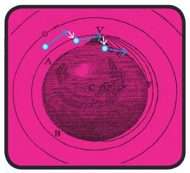
When the state of a particle is represented by a position and a velocity, the next position and velocity can be determined given a particular acceleration. The deviation in the trajectory has been exaggerated in order to show how integration introduces error.
The basics of a Verlet particle system are documented very well in Thomas Jakobsen's paper "Advanced Character Physics" (which you can find at www.teknikus.dk/tj/gdc2001.htm). The Verlet particle system is ideal for representing a ragdoll skeleton because constraints can be infinitely rigid without causing the system to diverge, thus the distance between joints can more rigidly be maintained. For this reason, you may find that a Verlet particle system is a nice thing to have around, even if you are not planning on doing any ragdoll physics.
The main idea behind the Verlet integration approach to ragdoll is that the positions of the joints are determined by point particles. The "bones" of the skeletons, represented by length constraints that enforce two neighboring particles, are an exact distance apart.
Extra length constraints can be added as necessary to prevent unnatural poses, as well as self intersection of the ragdoll. Updating the positions of the particles is relatively inexpensive, and calculating a length constraint is the equivalent of resolving a sphere collision, so the overall cost of updating the particle system is pretty low.
Once you've updated the positions of all of the particles, and then applied the constraints to ensure the appropriate distance relationships between them, it is time to do some collision. I decided to allow the particles to collide with the world as independent spheres, rather than trying to construct a closed collision volume that encompassed a ragdoll limb.
This decision was based on two factors. The first was the cheapness factor-sphere collision is much cheaper than some kind of ellipsoid or oriented bounding box collision. The second was that I succeeded in convincing the artists and designers who were creating the collision worlds to "play nice" with the ragdol -- meaning that they should try to make the static collision geometry as smooth as possible, with no really sharp kinks or protrusions that the ragdoll might get hung up on.
However, I still ran into pretty big problems using this approach. If you are using spheres to represent the collision volumes of joints, then the spheres generally need to be pretty small. After all, they are representing things like a hand, shoulder, or hip. Using such small spheres, I immediately began to notice that all of my collision routines would generally fail, due to the numerical imprecision introduced by fixed-point arithmetic. I'll cover some of the things that I learned in order to overcome these precision-related issues.
FX32 is a 32-bit fixed-point format that is used by the Nitro SDK with 12 bits of decimal precision. With 12 bits of precision, the smallest number that can be represented is 2-12 which is approximately 0.0002. It is a mistake to think that 0.0002 is indicative of the amount of precision to expect when performing calculations. Consecutive multiplications accumulate errors very quickly.
For notational convenience, I will define a fixed-point "unit": FX = 4096. A fixed-point number can be thought of as a multiplication of a real number by this unit, followed by truncation of the decimal portion. So if I wanted to represent 3.7 in a fixed-point format, I would have:
3.7FX = (3.7)*(4096) = 15155.2 == > 15155 = 3.6999FX
We see that we can't actually represent 3.7 in our chosen fixed-point format. Truncating to get an integer representation gives the nearest representable number that is less than 3.7. This error, due to the restricted representation, does not affect collisions until the size of the objects that you are colliding approaches the size of the smallest representable number-namely 0.0002. Indeed, for the sake of collisions, it is probably just fine to consider that the integer 15155 represents the fixed-point number 3.7FX. We will see that there is a much more significant source of error that occurs during calculations.
Using this FX notation, we can see that addition does not introduce any type of error, since normal integer addition can be used to add the fixed-point representations:
X(FX) + Y(FX) = (X + Y)(FX)
Thus, using integer addition to add together the fixed-point representations of the number X and Y results in the fixed-point representation of the number X + Y, which is exactly what we want. Again, if you want to be careful, you would specify that X and Y are representable numbers.
However, for the sake of collision in games we will just assume that all numbers are representable, until we start to collide things like molecules or bacteria. Now consider the case of multiplication. If we merely perform a normal integer multiply on the fixed-point representations of the numbers X and Y we would have:
X(FX)*Y(FX) = (X*Y)(FX*FX)
However, the right side of the equation is not the fixed-point representation of the number X*Y. We have an extra power of FX. To compensate for this extra power of FX, we can define a new fixed-point multiplication routine that performs an integer multiply on the fixed-point representations, and then divides by FX. For FX32s, dividing by 4096 is the same is shifting right by 12. A likely macro that performs a fixed-point multiply would look something like this:
#define FX_MUL(X,Y) (X * Y) > > 12
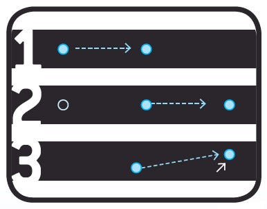
Verlet Integration can be conceptually understood in 3 steps. 1) The state of a particle is represented by its last 2 positions. The velocity vector is not stored, but it is implied by the positions. 2) We would expect the intertia will carry the particle an equal distance over the course of the next frame. 3) The position of the particle is modified slightly by the application of acceleration.
The surprising thing to notice is that with this definition of multiplication, the smallest number that can be multiplied by itself without resulting in 0 is 0.015. This is a very drastic decrease in the precision of representable numbers. This imprecision no longer affects collision of microbes and bacteria, but rather, the collision of things like ants. If your collision routine involves more than one multiplication, then it will affect collisions of things like hands or shoulders or hips. And this is what was causing all of my collision problems.
One solution to this is creating a new representation that allows more precision. For instance, I have recently built a fixed-point math library called FX32e, which has 27 binary digits after the decimal.
This obviously puts a very tight constraint on the largest representable numbers, but it is very useful for making objects that represent normalized vectors, quaternions, or rotation matrices, where all of the components are close to unity. However, this was not how I fixed the collision problems I was having. Rather, I found a couple of ways to cheat the precision difficulties that arise from multiplication.
The thing that causes the imprecision in the fixed-point multiply is the bit shift. Integer multiplication by itself will not introduce any error whatsoever, in the same way that integer addition does not. However, if we don't perform the bit shift, the result is not the fixed-point representation of the product that is desired. The question that needs to be asked is, "Why do I care?"
The answer is simple: We cannot add numbers or perform comparisons unless the two numbers involved belong to the same "FX space." The integer multiplication can be thought of as leaving the resulting product in the FX2 space, and the bit shift can be thought of as projecting the product back down into FX space. We cannot add or compare two numbers unless they are homogeneous in FX, or belong to the same FX space.
Consider a simple intersection test for two spheres:
bool SphereIntersection(Vec Center1, FX32 radius1, Vec Center2, FX32 radius2)
{
Vec d = Center1 - Center2;
FX32 r = radius1 + radius2;
FX32 d2 = FX_Mul(d.x, d.x) + FX_Mul(d.y, d.y) + FX_Mul(d.z, d.z);
FX32 r2 = FX_Mul(r, r);
return (d2 < = r2);
}
In this routine Vec is a Vector data type with fixed-point components, and FX_Mul is the macro that was defined earlier. The result of this function is a comparison of two numbers that are in FX space.
If instead of using the FX_Mul macro, we just used a regular integer multiply, the comparison would be between two numbers in FX2 space. An example of how to increase the precision (and add a slight speed boost!) is to merely replace the FX_Mul macros with a regular integer multiply:
bool SphereIntersection(Vec Center1, FX32 radius1, Vec Center2, FX32 radius2)
{
Vec d = Center1 - Center2;
FX32 r = radius1 + radius2;
FX32 d2 = d.x * d.x + d.y * d.y + d.z * d.z;
FX32 r2 = r * r;
return (d2 < = r2);
}
The lack of the bit shift means that the representable size of a sphere must be smaller to prevent overflow on the integer multiplication, but the routine will still provide correct (in fact much, much better) results. This is such an easy change to make, and had such a drastic improvement in terms of precision, that I immediately began to doctor up all my other collision code.
I developed some general rules for safely replacing fixed-point multiplies with integer multiplies:
- FX32 numbers accumulate a power of FX for every integer multiply, so keep track of the power of FX mentally or by comments in your code.
- Before adding or comparing two numbers, bring them into the same FX space. You can do this by multiplying the number with the lower power of FX by the appropriate power of FX. For instance, if you wanted to compare A in FX2 space with B in FX3 space, you would need to first multiply A by FX to get it into FX3 space.
- The larger the power of the FX space that you are in, the smaller the numbers are that you can represent. Thus, if you fear that you will overflow, you can bit shift to get into a smaller power of FX space.
- Don't pass your result out unless it is in regular FX space, i.e. FX1 space. (Unless you want to make a new data type for each FX space.)
- If the calculation is sensitive to precision errors, do everything in your power to never bit shift, i.e. try to replace every instance of FX_Mul with an integer multiply.
At some portions of my collision code I got up to FX5 before I was done with the calculation. Of course I had to use 64-bit numbers to do it without overflowing. I expected that doing this would slow the collision code down. Profiling revealed that this was not the case. This is probably because the fixed-point multiply defined in the Nitro libraries already typecasts to a 64-bit integer representation before multiplication in order to increase the range of representable products.
Before employing these tricks, the ragdoll would collide with the collision geometry about 1 percent of the time or less. After employing these tricks, the ragdoll collided perfectly. In fact, the last time I touched the collision code for the ragdoll was to implement these fixed-point tricks, and that was more than 10 months ago. The ragdoll went from being the worst colliding entity in the game to the best colliding entity.
After updating the physics of the Verlet particles, applying the constraints on the skeleton and colliding the independent joints with the surrounding environment, we have a skeletal pose that we need to somehow get the animation system to recognize.
The challenge of interfacing with the animation system stems from the fact that the joints of the ragdoll are being represented as points. A point is merely a position in space. However, the joint of an animation must also carry rotational information in order to properly deform the vertices of the associated skinned mesh. Because the particles that represent the joints of the ragdoll carry no such rotational information, it must be derived before we can properly interface with the animation system.
Another way to describe the problem is to consider that the joints of an animation are represented by matrices, and the joints of the ragdoll are represented by vectors. The vector that represents the position of the ragdoll joint can be inserted into one of the columns of the animation joint matrix, but we still need to determine what goes in the remaining three columns. The problem is figuring this out.
The three remaining columns of the animation joint matrix are the columns of a rotation matrix. These columns can be thought of as orthogonal unit vectors that define a basis in space. If we could somehow acquire at least two of these, the third could be determined from the condition of orthogonality.
The problem of determining the missing components of the animation joint matrix is reduced to finding an appropriate set of basis vectors in space. This set of basis vectors represents the "local" coordinate system of the joint-in other words the local x, y, and z directions of the joint.
It is a happy circumstance that when rigging a skinned mesh, a rigger will often align a child joint with one of the coordinate axes of the parent joint. Especially in the case where a joint has only one child, the local transformation of the child is generally translated along only one local coordinate axis.
In the case of the character that I was trying to interface with, this was generally the z axis. Therefore, in order to determine the local z direction of a joint, I merely needed to get a unit vector that pointed from the joint to the child joint.
How do we determine the second local coordinate axis? It won't be as easy as determining a unit vector that points from one ragdoll joint to another, since there is no guarantee that the second axis will always be orthogonal to the first one.
Consider that we have a human character standing in a "T-pose" with the arms straight out. The unit vector pointing from the shoulder to the elbow defines one of the local coordinate axes of the shoulder joint. To find the second coordinate axis, we could take a unit vector that points from the center of the character to a neck joint. Such a unit vector would define an "up" direction, and in this particular pose, it is orthogonal to the first local coordinate axis of the shoulder, and could therefore be used as the second coordinate axis.
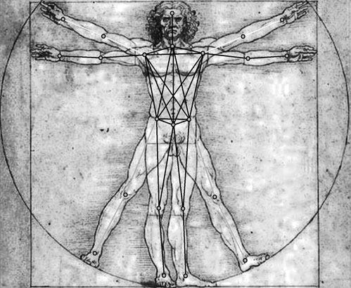
A Verlet-driven ragdoll can be considered a collection of particles that reside at the joints of the skeleton. These particles are constrained to lie within a fixed distance of each other in order to create rigidity in the ragdoll.
Once the arm pivots, the axis determined by the up direction is no longer orthogonal, and cannot be used as an axis. To fix this, we find the vector closest to the up direction that is orthogonal to the initial coordinate axis. We now have two orthogonal unit vectors, and the third can be determined by the requirement of orthonormality and the orientation (left/right handedness) of your desired coordinate system.
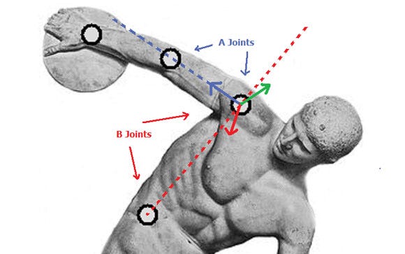
The A axis is the vector pointing from the first A joint to the second -- in blue. The B axis is not the vector pointing from the first B joint to the second. Rather, the B axis is normal to the plane that contains both the A and the B offset vectors. In the figure, this plane contains both the blue and red dotted lines. The C axis is determined by the right hand rule, i.e. it is the cross product of the other two axes.
We can extend this specific shoulder example to a generalized procedure for finding the local coordinate axes of an animation joint.
- Establish a pair of ragdoll joints that represents the first axis.
- Establish a second pair of ragdoll joints that represents the vector that is the goal of the second axis.
- Calculate the second axis by finding the unit vector that is closest to the goal, and also orthogonal to the first axis.
- Calculate the third axis by finding a vector orthogonal to the first two axes, that preserves the orientation of the desired coordinate system.
- Insert these three axes into the appropriate columns of the animation joint matrix.
Of course, if the parent/child transformations do not lie on local coordinate axes, then this procedure will not work. I developed this method based on the fact that I had observed that in the animation rigs I was working with, parent/child transformations almost always would lie on coordinate axes.
Of course this procedure could be generalized to specify local directions rather than local axes, but it might be better just to tell your rigger at the beginning of the project to place child joints on the local axis of the parent. (If you are in the middle of a project, and are in the mood for a fireworks demonstration, simply tell your rigger to re-rig the animation, then take cover before he explodes.)
To facilitate this general procedure, I incorporated a "Ragdoll Mode" into a pre-existing animation tool, where on a per-animation-joint basis we were able to define: 1) which ragdoll joints corresponded to the animation joints, 2) which ragdoll joints were used to determine which axes of the local coordinate transformation.
We called this process "setting up the brads," where the term brad refers to the set of information that pins-or brads-the animation to the ragdoll. When I was a youngster in elementary school, we would sometimes assemble skeletons out of paper bones. The bones were connected at the joints using brass brads.
This seems like a good justification for using the term "brad," but the real reason that it is called a brad is because one of our designers-Brad Moss-after making a vital suggestion, asked if we could name some code thingy after him.
The structure of the Brad goes something like this:
struct Brad{
int AnimJoint; //index of the animation joint
int RagdollJoint; //index of the corresponding ragdoll joint
int JointA1; //The first pair of ragdoll joint indexes that define the "A Axis"
int JointA2;
int JointB1; //The second pair of ragdoll joint indexes that define the goal
int JointB2; //of the "B Axis"
int AxisA; //References an enum that determines if A is the x, y, or z axis
int AxisB; //References an enum that determines if B is the x, y, or z axis
Matrix JointMtx; //The most recently calculated joint matrix
};
The main purpose of this structure is to contain all of the information required to construct a transformation matrix in animation space. After updating the position of the ragdoll is complete, after applying constraints and collision, we loop over the list of Brads, calculate the transformation matrix and store it in the JointMtx element of the structure.
In the general cycle of an animation system, the joints are represented as transformations, but the form of the transformation varies at different points in the cycle. Here is an oversimplified example of the evolution of a single joint through an animation cycle:
- Keyframe Blending. Interpolate between two key frames to get the local rotation and translation-local means the transformation relative to the parent joint.
- Animation Blending. Interpolate between the transformation values for two different animations-still the transformation is local.
- Expanding. Expand the skeleton so that all the joints are expressed in animation space-now the transformations are no longer local. The expansion is performed simply by multiplying the local joint transformation matrix by the expanded parent transformation matrix. If this joint is the first joint in the skeletal hierarchy, then the parent transformation is just considered to be the identity.
- Prepare for Skinning. Prepare the list of transformation matrices for skinning by multiplying by the inverse value of the transformation in the bind pose.
The appropriate point to insert the transformation matrix calculated by the brad is in the "Expanding" phase. When the ragdoll hijacks this expand phase, it looks to see if the joint has a corresponding brad. If it does, then it does not calculate the animation space representation of the transformation as normal, rather it just inserts the JointMtx that had been previously calculated. This method was the suggestion made by Brad Moss that immortalized his name in our codebase.
The animation rig that I used had on the order of 25 bones. I had 15 ragdoll joints with almost 30 length constraints. I would collide each ragdoll joint individually as a sphere using a swept sphere algorithm. The total amount of time to update the Verlet particles, apply the constraints, and collide and construct the brads took around 2000-2500 microseconds.
2500 microseconds is not really a cheap operation, but is definitely manageable considering the 15,000 microsecond allotment of a 60Hz cycle. Actually, we found that when the character was in ragdoll, we could short circuit some other parts of the character update cycle, and it turned out the entire character update cycle went slightly faster when the character was in ragdoll. As such, ragdoll performance never ended up being an issue for us.
Of all of the problems that I faced while implementing this technology on the DS, the largest problem was the psychological aspect. Everyone around me, including myself, believed that ragdoll was way too expensive for the teeny little DS.
It seemed like a long shot when the idea was first suggested, and we would often discuss how low we were willing to let the frame rate drop in order to have it in the game. We pressed forward on the assumption that there was only a 5 percent chance that it would actually work well. The greatest lesson I learned from this experience was that sometimes 5 percent is enough to believe in.
Read more about:
FeaturesYou May Also Like