
Trending
Opinion: How will Project 2025 impact game developers?
The Heritage Foundation's manifesto for the possible next administration could do great harm to many, including large portions of the game development community.
Many games, even on current "next-gen" hardware, render particles using camera facing quads - veteran coder Krazanowski (Tomb Raider: Anniversary) suggests a neat alternative solution using pixel shaders and a little bit of math.

Many games, even on current "next-gen" hardware, render particles using camera facing quads. In many cases these particles are used to represent volumes of many smaller microscopic particles. These volumes typically are simulated simply by determining how much contribution they present to the view using a simple blend function. This blend function defines how much the simulated volume of particles obscures the scene behind them.
Although this method has been employed in games for many years, this article defines a method using shader technology to more physically represent these volumetric particles. This method will give a more accurate visual representation of the simulated volumes as well as potentially decreasing the necessary number of particles, which in turn will help to improve render performance.
It should first be stated that the method defined in this article is limited to particles that represent volumes of sub-particles. It is also noted that the analysis that is to follow assumes a uniform density of the particles. There are methods that would allow the user to define more complex density functions, but that will not be covered here.
Many games have tried to represent environmental effects such as dust, mist, gases, energy volumes etc. using the same method for years. Essentially they define how much a particle obscures the rendered environment behind it using the alpha channel in the texture.
The alpha channel can be used to define transparency or opacity but in either case the algorithm is the same, the resulting pixel colour (Cr) is interpolated by some function (A) between the already rendered environment colour (Ci) and the particle colour (Cp). In most cases I have seen, the alpha channel defines the A value and the function is:
Cr = A*Cp + (1-A)*Ci;
This is the basic interpolation function.
So what is wrong with this function? It uses two adds and two multiplies and in most cases is handled in hardware. It is simple and easy to use.
For the most part, semi- transparent camera-facing polygons rendered using this function represent the macroscopic volumes that simulate the microscopic particles as the user intended. Assuming the art is correct, they are sorted correctly from back to front and the quads they are rendered to don't collide with any other quads in the scene, the visual effect is sufficient to simulate microscopic particle volumes.
Now the art correctness is handled by the art department, and many engines handle sorting of the particles as they are rendered, so there is no problem there. How about the problem with them colliding with other geometry? A consequence of rendering all the particles as camera facing polygons is that the particles don't collide with each other almost all of the time. We can't make the same claim about the particles' collision with other geometry in the scene.
In some cases, the particles can be rendered without considering the depth buffer, but that assumes that nothing will obscure the particles themselves from the view. In other cases, there might be the CPU time to handle each particle's collision with the world, and simply make sure they don't ever encounter this case. For most games, the artifacts caused by particles and the environment have been considered an acceptable artifact.
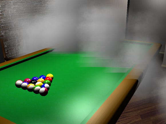
Fig 1. Example from the Chrome Dragon Engine using the basic modulate blend mode render method for smoke particles
Unfortunately, due to the visual aliasing problems that arise from this method of particle rendering, art teams have developed some problematic procedures:
Typically, on a first pass of a volumetric particle effect, the artist will create the particles the size and density that best represents the visual quality that is appropriate. When the effect is added to the game, it typically becomes immediately apparent that the actual particles are geometrically too big.
When they render, the artist is required to tweak the visual look away from the intended visual quality, and retrofit it to avoid any possible collision with environmental geometry.
In cases when it is necessary to have particles close to geometry, the artist is required to not only artificially shrink the particles to avoid noticeable aliasing artifacts, but typically increase the number of particles to account for the now-empty space. As soon as they increase the number of particles they must change the alpha values in the function to account for the increased likelihood of overlapping particles.
This decreases the intended resolution of the alpha channel (potentially causing visual effects itself), makes the effect itself more grainy and exponentially dense, and worst of all, requires the artist (and possibly a programmer) to waste time tweaking to account for the inadequacies of the basic interpolation function.
Most games consider the collision artifacts of semi-transparent particles and the environment acceptable. This is due to the abundant hardware that has been available that performs the basic interpolation functions.
In Software Development Kits (SDKs) such as OpenGL or DirectX, there have been render states defined that simply do the blend function with one function call and have been available for many years. Unfortunately, art departments have been working overtime trying to get basic particle effects in the game and looking correct to account for this one line of code.
In recent years, there has been a significant leap forward with the software developer's ability to define the functions used to render a scene in the hardware: shaders. Even on cheap consumer graphics hardware, the software developer can define almost any function imaginable (usually only limited by available registers and functions made available to the shading language).
Using pixel shaders, render-to-texture technology and a little bit of math, I claim that we can more correctly simulate the volumes that the particles were intended to represent.
The problem with current methods of rendering particles to represent volumes is that, like most geometry in games, they are not volumes. They are camera facing planes rendered with the intention to never show their depth.
Now we all know that their depth does indeed show itself if that simulated depth ever comes close to other geometry defined with real depth. The problem arises due to the fact that we are aliasing the depth into those camera facing polygons. We are taking the visual characteristics of a volume in space and flattening it to a plane, then rendering the plane back in a world with real volume characteristics.
Let's assume that we don't actually want to do this. Let's also assume that we don't want to significantly change the art pipeline the artist would perform on their first pass.
What do we need to better represent these volumes? Assumptions and math. For the purposes of this article, the following assumptions are used:
That the contents of each particle are intended to be uniform density. That is if we were to take a sample in the actual volume that the particle texture was rendered from, it would be the same density as every other sample within the volume.
That there are exactly two real-world boundaries implicitly defined for each pixel in the source texture. The boundaries are the near and far extents of the volume that the pixel is intended to represent.
That there exists a plane that defines a mirror image of the boundary of the volume for each pixel. (This assumption will disappear in a later example).
That the user has access to the actual depth values rendered for the scene occluded by the particle within the pixel shader.
We should also assert that the pixels rendered on the poly implicitly represent volumes from the camera's perspective.
The idea is to take the drawn poly and define a pseudo volume around it. This volume is defined by the extents of the poly, extruded in the direction the camera is facing.
For the following example, the poly is extruded both towards and away from the camera by some distance D to define the volume.
The original poly defines the mirror-image plane P(mi) and the alpha channel in each pixel defines to what extent the sub-particle boundary B(sp) deviates from the P(mi). In practice the volume would be defined as the poly extruded away from the camera only to make full use of hardware clipping.
This is due to the fact that pixels that are rejected due to being occluded will never get calculated for the near region of the volume.
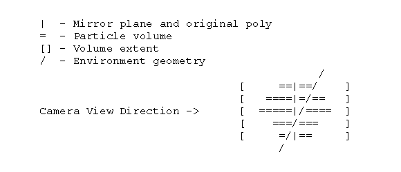
Fig 2.
Now for each pixel rendered in the particle, we have extents along all the view rays through those pixels that define the collision information necessary to remove the visual aliasing caused by a planar particle. There are at least two ways to consider the information provided by the alpha component of the texture:
As an average density of microscopic particles over the range from the front to back of the volume. I will call this method the average density method.
As relative the density that relates to the extent of the microscopic volume along the ray represented by the pixel. I will call this the density extent method.
In the shader we will need the depth of the environment at the given pixel. This could be passed in as texture information from a previous render-to-texture stage. I will call this EnvironmentDepth.
We will need the pixel position of the original poly that will define our mirror plane. This can be propagated from the vertex shader, and I will call it ParticleDepth.
We will also need a function to define the mapping from alpha value to real-world depth do define our deviation extent, I will call it DeviationExtent. The deviation extent will likely be constant across the whole poly and possibly the whole particle effect.
We will use the existing particle texture unmodified with its colour and alpha values as they were originally defined.
We will define a global opacity/transparency function that will be used to relate the maximum particle density and relates the actual colour transmission through the volume which I will call VolumeAlpha. This function is used to define the maximum transparency/opacity the extents of the volume will allow.
As a consequence of this, we may be able to increase resolution in the transparency calculation by normalizing the alpha channel in the particle texture and globally modulate it with the VolumeAlpha value.
This also allows us to globally change the transparency of all the particles.
The alpha channel now defines the deviation ratio from the mirror plane to the extents. The particle extents from the camera in real world coordinates is defined as ParticleDepth -/+ DeviationExtent. The actual particle volume boundary is defined as ParticleDepth -/+ TextureAlpha * DeviationExtent.
With these tools we are now able to define a more accurate representation of the occluding properties of particles with objects behind, within and in front of the particle.
I will calculate the actual alpha value based on the previous derivation.
FarParticleDepth = ParticleDepth + TextureAlpha * DeviationExtent * 0.5;
NearParticleDepth = ParticleDepth - TextureAlpha * DeviationExtent * 0.5;
The average density calculation:
// Get the Environment Depth in terms of the volume, values we are interested
// in are in the range 0 to DeviationExtent.
Alpha = (EnvironmentDepth – ParticleDepth)/(DeviationExtent);
// Clamp the value to 0..1
Alpha = VolumeAlpha * Clamp( Alpha, 0.0, 1.0 );
// Get resultant pixel
OutputColour = Alpha * ParticleColour + (1.0 – Alpha) * SourceColour;
The density extent calculation:
// Get the Environment Depth in terms of the volume, values we are interested
// in are in the range 0 to DeviationExtent.
Range = (EnvironmentDepth – ParticleDepth)/(DeviationExtent);
// Scale this range based on the alpha value defined for the pixel
Range = Range * (1.0/ParticleAlpha);
// Normalize the value to -1..1
Alpha = Clamp( Range, -1.0, 1.0 ) * 0.5 + 0.5;
Alpha = Alpha * VolumeAlpha;
// Get resultant pixel
OutputColour = Alpha * ParticleColour + (1.0 – Alpha) * SourceColour;
These algorithms will perform the simple interpolation method as has been performed in hardware for years for cases when no collision occurs. For cases when the particle's volume does collide with environmental geometry, this algorithm will ramp the particle's contribution to the background contribution based on the amount of the volume obscured by the background.
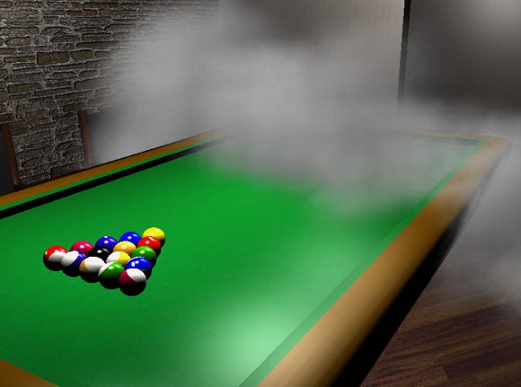
Fig 3. A screen grab from the chrome dragon engine using the average density method. (Using the exact same art as in Fig 1.)
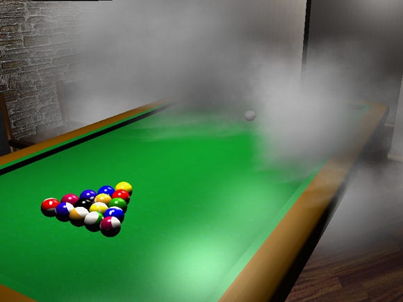
Fig 4. A screen grab from the chrome dragon engine using the density extent method. (Using the exact same art as in Fig 1.)
One thing to keep in mind when implementing this particle rendering method is that you are rendering a representation of a volume and that the depth of the volume is most likely related to the other dimensions of the particle. It is probably appropriate that some function relating particle size to depth be defined on a per-particle basis.
An additional note about the density extent method is that the volumes will use the alpha channel to define the extents of the volume on a per-pixel basis. Unfortunately most art defining particles to simulate volumes use a gradient method from the center of the texture, which will define the volume roughly as a wedge shape.
As you can see in Fig 1, many of the particles seem to have a kind of soft-aliased look to them with the unmodified art. For this approach to have visual merit, the source art may need to have the alpha component of the texture defined with true volumetric properties.
This approach can be extended to:
Encode a deviation from the mirror plane into one of the channels of the texture. This allows the author to define an alternate depth median, by specifying the mirror point as a deviation from the original particle plane.
Encode volume normal information into the other 3 channels of the texture and pass in the volume colour as uniform for the whole particle. This allows some real-time lighting information to be rendered as part of this shader.
Current particle rendering methods for volumetric particles in games are flawed, its acceptance will die out quickly and it is fixable using shaders in current generation hardware.
What is more, the proposed modification to existing rendering methods require few changes from the art department, adds a small amount of registers to the shader, adds a small number of shader instructions, and may not require significant changes to the existing rendering engine in your game.
Most importantly, the rendered particles will better represent the intended vision the artist while allowing for the number of particles to be decreased in the process.
Bibliography
Spherical Billboards for Rendering Volumetric Data - ShaderX 5 - Thomas Umenhoffer, Laslo Szirmay-Kalos and Gabor Szijarto
Volumetric Post-Processing - Game Programming Gems 5 - Dominic Filion, Artificial Mind & Movement, and Sylvain Boissé, Motorola
OpenGL Shading Language (Orange Book) - Randi J. Rost
[EDITOR'S NOTE: This article was independently written and commissioned by Gamasutra's editors, since it was deemed of value to the community. Its publishing has been made possible by Intel, as a platform and vendor-agnostic part of Intel's Visual Computing microsite.]
Read more about:
FeaturesYou May Also Like