Daily news, dev blogs, and stories from Game Developer straight to your inbox
Sponsored By
Featured Blog | This community-written post highlights the best of what the game industry has to offer. Read more like it on the Game Developer Blogs.
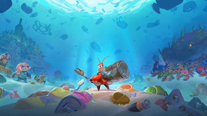
Getting the World of "Sprint Vector" Over the Finish Line (by Kevin Andersen, Survios Technical Artist)
Survios Technical Artist Kevin Andersen discusses how multiplayer racer "Sprint Vector" brought a new level of design challenges, most notably: how do you design an aesthetically distinct world that's easily readable and render-able at 100mph--in VR?
17 Min Read

By Kevin Andersen, Survios Technical Artist
"Sprint Vector" was an adventure to make. As I originally drafted this, project champion and lead designer Andrew Abedian looked like he crawled out of a shallow grave to take a nap in an office chair, producer Chris Thompson was pouring Red Bull in his coffee, and Console QA lead Kris Gruchalla was half-awake doing butterfly-knife tricks to an audience of frightened interns. The game itself was a hugely ambitious project with massive maps, eight simultaneous players all with unique character models, loads of effects and UI elements, an original setting and story, two fully-voiced commentators, and probably some other things―all delivered straight to your face in virtual reality, sporting a brand spanking new Fluid Locomotion System that tricks your brain into thinking you deserve to go this fast. Indeed, bringing "Sprint Vector" from concept to reality was an immensely educational, utterly infuriating, and beautifully rewarding process for the whole team. The solutions we found in doing so should be well worth reading about, not just for other game devs, but also for enthusiasts, fans, and the next-of-kin to the few QA testers who caught fire.
So here―from the initial block-out phase of the level designs to the finalized lighting and effects being frantically tuned at the last minute—the "Sprint Vector" team presents a nearly-interesting account of development’s many technical hurdles and how they were chainsawed. Some jargon may be foreign to the average reader, so if you’re unsure of something, just assume it was very impressive.
Arting the Game and Establishing "the Look"
The team wanted to do something bright, with a fun, comic-book-y feel that wouldn’t overwhelm the player with details as they zoomed through it all at great speeds. A simple, colorful, cartoon world was the antidote to Raw Data’s dark, detailed, sci-fi aesthetic. Seriousness summarily defenestrated, we adopted a new standard of zany wackiness and wacky zaniness, with hints of madcap shenanigans and offset with notes of whimsy and rich sandalwood.
Keeping everything simple—and immediately readable at 50 mph—required environments to be made up entirely of big, obvious shapes and solid colors. To that end, the use of textures on environment assets was eschewed and the era of vertex color began. "Sprint Vector’s” world assets rely almost exclusively on vertex colors for diffuse and roughness/metallic values on the majority of their materials. They also use sharp-edged geometric detail to denote surface features like sand and rocks. This ultra-simplified style had both pros and cons vs traditional game-art production.
Pros: Fewer textures means less VRAM used and faster loading times. Making things quickly and authoring their colors all in maya, unifying color and roughness schemes throughout the game, and only needing a single UV channel (for lightmaps), since no textures also means no worrying about tilling or seams.
Cons: Using geo, instead of normal maps, for every feature inflates the vertex count, which is already doubled in any VR game. Also, hard edges (split vertex normals) on everything then further triples the vertex count, sending the transform cost and mesh memory allocation into the bad zone of sadness.
Every triangle that makes up a given surface gets its normal (facing direction) from the information contained in its three vertices and any one vertex can only have one normal. If you want an edge between two faces to be sharp, you have to split the vertices at its points so each face is getting its normal information from its own separate set of verts that are now just sharing locations with the vertices from the surrounding faces. That vert-splitting is not free; you pay the GPU cost of transforming every vertex no matter where it is and the average asset’s vertex count can triple with just that one change. As stated, a VR game’s geometry must be transformed twice for a stereo camera, so now you’re looking at 6x maya’s stated vertex count, throttling the GPU and making tech-artists like me seethe with rage at the hubris of it all.
Another issue with the hard-edge approach was that LODs became really ugly really fast. The swap from hi-res to low-res can be hidden somewhat by averaged (smooth) face normals, but when a hard-edge disappears everyone sees it. For that reason, Unreal’s auto-generation of LOD meshes uses normals to determine which edges to delete while simplifying a mesh, and it just can’t make good decisions when all the edges are sharp. We needed some other way sharpening the normals on our level geometry, so I made a material that altered the way surface normals are read in the pixel shader.
The block on the left is the model as it was imported to the game, with all of its vertex normals averaged. This keeps the vertex count as low as possible but makes it look like a sad blob of nothing. The block on the right is the same asset with the edge hardness restored, bringing the details back so one can see the individual bricks. Its surface normals have actually been faked in the pixel shader with the material logic below.
The GPU renders scene pixels in 2x2 quads that allow it to compare a surface’s UV coordinates at 4 points and use that distance to determine the proper mip level to use for the texture lookup. The bonus here is that this also allows other properties of pixels to be compared to each mid-render by using the DDX and DDY functions in the material graph. These instructions return the delta between a pixel and its neighbor along the screen’s x or y axis for the given attribute. In this case, the attribute we want is the pixel’s position in the world. The deltas between these positions are therefore useful tangents and bitangents from which a surface normal can be derived by normalizing their cross product. The result is then plugged into the material’s Normal input (where a normal map texture would typically go). Another advantage of this technique is the ability to blend between hard and smooth normals with vertex alpha, or over distance to hide LOD popping. This method did cause some annoying noise on metallic objects when you get up close, but that was acceptable considering the savings.
Populating A Cartoon World
The characters needed more detail to give them real personality, so their design simply could not be flat-color and sharp edges like the rest of the game world. They were all made by one mister Damon Woods in the traditional Maya/ Zbrush/Photoshop workflow, and they all had the full complement of texture maps.
Unreal’s default lighting model, however, was just not equipped to make them look like anything but plastic, wood, or metal. Also, since the game is forward-rendered (for that sweet sweet MSAA), a subsurface-scattering material was also not an option, even if we wanted one. But we totally didn’t. So there.
In the above comparison, the Cosmo on the right looks like an action figure. In still-renders that’s not bad, but when it moves around in VR it looks creepy as hell. At this point, a majority of the important effects had already been made, and were all purely cartoony. They looked great in our simplified environments with their hand-painted skydomes, and they really sold the overall aesthetic. Those plastic characters, however, clashed with the effects in a way that made it look like they both came from two different downloadable asset-packs and we just slapped them together in the same game. We needed these characters to render less like haunted mannequins and more like comic book illustrations, using a stylized lighting mode that did their design and modelling justice. There is no cel-shaded lighting model in Unreal 4, so we had to make one. It was time to prototype.
You’ll notice that the above material graph is unlit and only has an emissive input. That’s because this is not yet a real shading model; it only provides an example of what the result would be if this logic were used to light a surface from a single light source. A stepped, off/on lighting model would cause obvious aliasing that would not be solved with MSAA and would also get worse as the lights got brighter. Instead, I aimed to crunch the basic lambertian falloff down to a thin gradient between larger areas of fully-lit and fully-dark, without ever making the transition pixel-sharp. To do this, I simply remapped the dot product of light vector and surface normal (lambert lighting model) from -1:1 to -n:n (where n = the bias of the lit and unlit areas toward each other), and then clamped the result back to 0:1, which would then be multiplied by the product of base color and light color for the final result for that light. The rim highlight was a simple fresnel that scaled up the direct lighting contribution as it approached an edge, then crushed the resulting gradient in the same manner to match the style. An additional ambient rim light was later added as a material function to some materials as well.
Getting this logic into an actual lighting model, i.e. usable with any number and kind of lights, requires making significant changes to the rendering code. I’m not an engineer, or even a first-try high school graduate, but I’ve used Unreal long enough to remember when UE3 (UDK) had a custom-lighting input in its material editor that allowed you to construct your own lighting model purely from your own node-logic. UE4 doesn’t give you access to any of that anymore, but you can access two specific lighting contributions: the atmospheric sun light’s direction and its color. With those as representatives of any given light, I constructed the pictured material graph to develop the look of a hypothetical cel-shaded lighting model before handing it off to our rendering engineer, Eugene Elkin, to do all the actual work-work. Eugene will take over the next section, to provide his own insight into the rest of this process, since I’m not a programmer and you know I’d just be making things up like I have been for five paragraphs now.
Adding the Toon Shader to the Engine (with Senior Software Engineer Eugene Elkin)
With the shading model’s proof-of-concept prototype complete, it’s time to implement that shading model in code. While this is not a difficult task, it can be a bit time-consuming due the number, and varied locations, of small engine changes that are required to add all the proper variables.
The easiest way to add a new shading model to the engine and editor is to follow the example of an extant shading model. The very first thing you’ll want to do is add your new enum entry to the EMaterialShadingModel. You will have to use the search function to follow around some other enum entry to add your new enum to each place it exists. There are about seven or eight places you’ll need to do this, to account for everywhere your shading model could be referenced, in-editor or at runtime.
With the Shading Model enum propagated, you should have all the proper shader defines created as well. It’s time to add our shading model’s variables. The process here is similar as mentioned above. Add your enum entry to the EMaterialProperty. Once again use another entry from EMaterialProperty to find all the places that need to be edited.
Once variables and shading model variables are created they need a good home inside the shader code to actually perform some logic. We start off in the FPixelShaderInOut_MainPS of BasePassPixelShader.usf by saving off our shading model’s variables to GBuffer.CustomData.
#elif MATERIAL_SHADINGMODEL_TOON_LIT
GBuffer.ShadingModelID = SHADINGMODELID_TOON_LIT;
GBuffer.CustomData.x = GetMaterialToonLitRoughness(MaterialParameters);
GBuffer.CustomData.y = GetMaterialToonLitBias(MaterialParameters);
Once the roughness and bias variables are cached, we can use them to perform the shader calculations specified in the prototype. The toon shading equation is run once in the float4 GetDynamicLighting() and again in float3 SurfaceShading() to affect diffuse and specular respectively.

After compiling the editor and engine, artists will now have a new shading model to choose, and additional properties to tweak in the material editor. The previously unlit prototype material’s logic has been translated into a functioning shading model that can work with any number or kind of dynamic lights! Now the tech-art lead will stop bringing it up all the time when you’re on smoke break.
Atmosphere
HAY GUYZ IT’S KEVIN I’M BACK. You know what I’m gonna say so here it goes: it’s time we sat down and had a serious discussion about the clouds in "Sprint Vector." They’re neat. They’ve been a hot topic ever since I insisted they were just now. Nearly one person has been asking how they came to be, so here’s the full hot story:
Concept artist Hadi Jalali made a cool hand-painted skydome for the E3 2017 demo, and we knew we couldn’t just re-use that for everything, but we also didn’t have the time to make unique, high-res, hand-painted skydomes for every map in the game. Part of my job—well most of it, at this point—is lighting all the levels, and that usually includes a lot of material, texture, and effects work as well. One of the highest ROI assets I made in that endeavor were the damn clouds.
Above, you can see one of the cloud meshes and its vertex colors. I used xNormal to bake the AO and translucency maps, placed them into the red and green channels of a texture, then went back into maya and imported that file as a vertex color set for the mesh. This way, neither texture is ever actually used in game.
Populating the sky with clouds that sell the game’s atmosphere and aesthetic - but didn’t kill performance - would require some additional planning and material work. I knew it had to be an extremely cheap material, but it also had to lend itself to myriad lighting conditions while always looking as stylized and colorful as the rest of the game world. All the clouds are the same 3 meshes, each with 3 LODs, rotated and flipped all over the sky in super artsy ways. I mentioned previously that UE4 gives you access to the sunlight’s direction and color in your material setup, and that fact was again crucial to getting the cloud material to work in multiple levels with different outdoor lighting:
As you can see, this material is also unlit and only has an emissive input. The clouds are affected by the sun, but only via AtmosphericLight nodes in the graph here; there is no actual lighting happening. Since the vertex colors contain the AO and thickness of the cloud meshes, I used that information to fake the ambient lighting and also the sunlight shining through them when they are near the sun. Translucency was simulated in the material by wrapping the sunlight influence further around the cloud from the angle of the light, attenuating it by both the thickness map (vertex red channel) and how close the cloud is to blocking the sun in the player’s view (dot product of camera vector and AtmosphericLightVector). The ambient light around the cloud was a simple color parameter multiplied by the AO (vertex green channel). This material, in concert with the ‘directional in-scattering’ feature of exponential height fog, proved fantastically versatile and was used on almost every level with an open sky.
Lighting The World
"Sprint Vector" doesn’t have laps; the tracks are linear start-to-finish courses. We made reversed versions of all of the maps, which opened up possibilities for new shortcuts and falling/climbing sections that you’d never see going one direction. Having a reversed version of a map also requires a whole new lighting scheme to keep things fresh and expand the game’s visual palette from one race to another.
Unreal’s static lighting solution is immensely scalable and lends itself to combination-approaches that mix both static and dynamic lights. While static lighting is pre-computed and has a very high quality and performance ceiling, it is still static and will not work with the toon-shader as the characters pass by sources of light. Extra care had to be taken to ensure that the number of dynamic lights and their influence radiuses were kept to a minimum while still ensuring that the characters had at least one dynamic light on them as often as possible. Since “Sprint Vector” takes place during a wacky game show, the tracks were littered with neon markers to direct the player and advertise wonderful products like Andew Deodorant (a nod to an in-studio meme related to Lead Designer Andrew Abedian and an unfortunate typo on his GDC badge). Unreal Lightmass’s emissive area light feature allows these glowing meshes to cast their light into the environment without me having to manually place thousands of tiny static lights.
The sun was always a stationary directional light with ‘Area Shadows’ DISABLED. This kept the static shadow maps sharp and made the lighting look cartoony. The dynamic shadows cast by the players had to be low-resolution for performance, but the blurriness clashed with their shading, so the shadow filter sharpening had to be increased. This revealed more noise in their low-res shadow map as they animated, but it kept their shading and shadowing aesthetically consistent. The sun is the only light that casts a dynamic shadow, except for the spotlights in the intro.
One ofthe optimizations made possible by forward lighting mode is that materials will default to a much cheaper version of the reflection environment that does not interpolate between reflection captures’ various cubemaps, but rather just chooses the closest one and uses that. This greatly decreases lighting instructions and the cost of reflection captures, but requires you to place more of them and be more careful to avoid situations where one section of floor has an unexplained pink light from being too close to a reflection capture in an adjacent room. Another issue with reflection captures is that they are refreshed on level-load. That would be fine, but our levels have fog that changes its density and color as you enter and exit areas. Those areas would then have that fog in their reflections and make shiny objects glow the wrong color when you get there. To fix this, we made a small engine change to allow reflection captures to use a few of the same show flags as scene captures. Disabling fog in the captures solved the issue.
Conclusion
"Sprint Vector" was hard to make.
Read more about:
Featured BlogsAbout the Author(s)
You May Also Like