Daily news, dev blogs, and stories from Game Developer straight to your inbox
Sponsored By
Featured Blog | This community-written post highlights the best of what the game industry has to offer. Read more like it on the Game Developer Blogs or learn how to Submit Your Own Blog Post
Create your own Inverse Dynamics in Unity
Looking to add some physics to your player's avatar, your game enemies, or NPC's? This article will show you how to implement humanoid physics into your Unity game.
6 Min Read

This was originally published here.
Create your own Inverse Dynamics in Unity
Are you looking for Inverse Dynamics in Unity or Unity’s Physics engine (PhysX)? It doesn’t exist as far as I can tell, but it does exist for other physics engines, such as Bullet and possibly ODE (Open Dynamics Engine). Luckily, Inverse Dynamics is not too hard to implement in Unity.
Unity does have an IK (Inverse Kinematics) feature, but that only helps you with kinematic motion and not with physically-based motion. You don’t want your humanoid character to just move, you also want him to move realistically. That’s where Inverse Dynamics comes in. Before we dive into the implementation details, you can find an Overview of Inverse Dynamics or Overview of Inverse Kinematics.
In this article, first, we’ll go over an abstract algorithm, so you understand the high-level procedures to implement the Inverse Dynamics algorithm. Then, we’ll go over the actual equations you need to implement the algorithm. Finally, we’ll go over the base cases necessary for this recursive algorithm.
Abstract Algorithm
The ultimate output of Inverse Dynamics are the forces and torques of the rigid body required to make a movement — with the inputs being the orientations, angular velocity, and angular acceleration at each joint. One algorithm to achieve this output requires a forward iteration from the root link to the final outboard link, and then a backward iteration from that final outboard link back to the root link. It is called the Recursive Newton-Euler Algorithm (RNEA). It was developed by Luh, Walker, and Paul in 1980, and it continues to be championed to this day by other researchers such as Featherstone and Mirtich.
void InverseDynamics() {
    RootToFinal(); // PartOne
    FinalToRoot(); // PartTwo
}
The first part iterates from the root limb to the final limb. For each limb, it computes the angular velocity and angular acceleration of the limb. The computation for the angular velocity and angular acceleration of each limb is based on the angular velocity and angular acceleration from its inboard neighbor limb. For each limb, it computes the linear acceleration at the inboard joint. Computing the linear acceleration at the joint is based on the angular velocity and linear velocity from its inboard neighbor limb.
This process of computing angular and linear velocities/accelerations for each limb (from root limb to final limb) is called velocity/acceleration propagation. This is because each velocity/acceleration is based on the velocity/acceleration from the neighboring inboard limb (in other words, the previous limb).
The rest of the computations for each limb are based on the limb’s own angular velocity, angular acceleration, and linear acceleration at the joint. For each limb, it computes the linear acceleration at the limb’s center of mass. For each limb, it computes the internal forces for each limb. For each limb, it computes the internal torques for each limb.
/* Part One (Abstracted via Functions) */
void RootToFinal() {
    currLimb = rootLimb;
    prevLimb = NULL;
    while (currLimb != NULL) {
        // Angular
        currLimb.computeAngularVelocity(prevLimb);
        currLimb.computeAngularAcceleration(prevLimb);
        // Linear
        currLimb.computeLinearAccelerationAtJoint(prevLimb);
        currLimb.computeLinearAccelerationAtCOM(currLimb);
        // Forces
        currLimb.computeLimbForce(currLimb);
        currLimb.computeLimbTorque(currLimb);
prevLimb = currLimb;
currLimb = currLimb->outboardLimb;
}
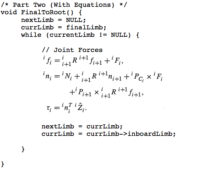
}The second part iterates from the final limb to the root limb. For each limb, it computes the joint force based on the joint force from its outboard neighbor limb. For each limb, it computes the joint torque based on the joint torque from its outboard neighbor limb.
The second part is much simpler than the first part, as you can see.
/* Part Two (Abstracted via Functions) */
void FinalToRoot() {
    nextLimb = NULL;
    currLimb = finalLimb;
    while (currentLimb != NULL) {
        // Joint Forces
        currLimb.computeJointForce(nextLimb);
        currLimb.computeJointTorque(nextLimb);
        nextLimb = currLimb;
        currLimb = currLimb->inboardLimb;
    }
}
Actual Equations
You might have noticed that each computation in the pseudo-code above is abstracted by a function. Luckily, each of those functions is merely a one-liner equation. That said, each one-liner of code is packed with mathematical cross products, derivatives, and notations. We’ll explain all of the math in the next article (coming soon) if you’re interested, but for those that are fine with a plug and chug algorithm, this article provides the pseudo code for Inverse Dynamics with all the required math equations.
First, here are some definitions and figures:
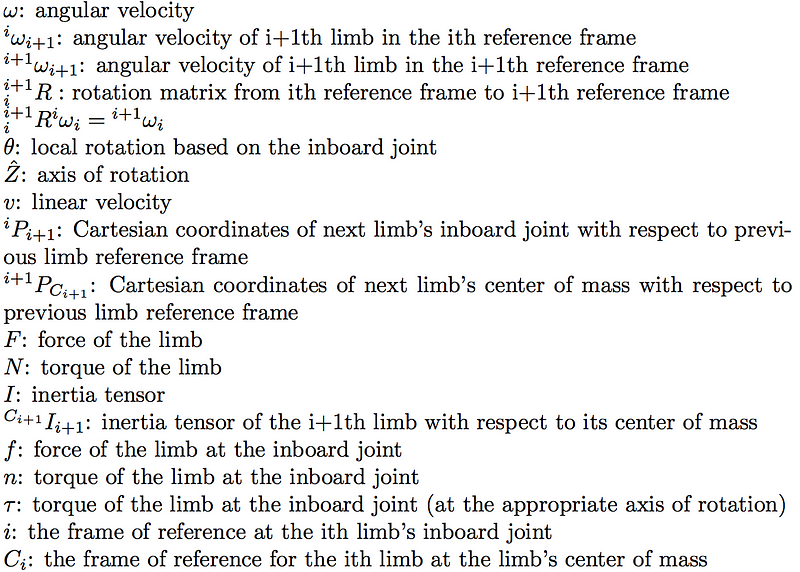
If some of the prefix and postfix notations didn’t make sense, here is a diagram to help clarify:
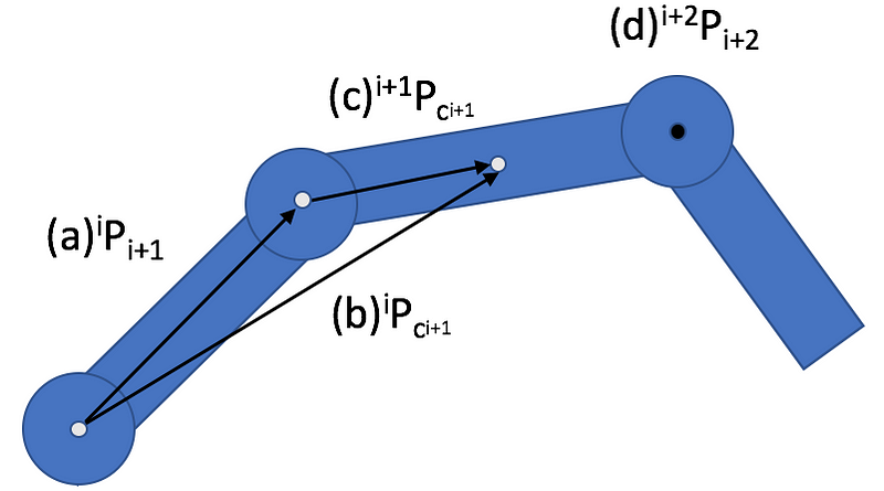
Examples of points with different frames of reference. (a) Point of i+1th inboard joint with respect to ith reference frame. (b) Center of mass of i+1th limb with respect to ith reference frame. © Center of mass of i+1th limb with respect to i+1th reference frame. (d) Point of i+2nd inboard joint with respect to i+2nd inboard joint.
With that in mind, we move onto the actual algorithm:
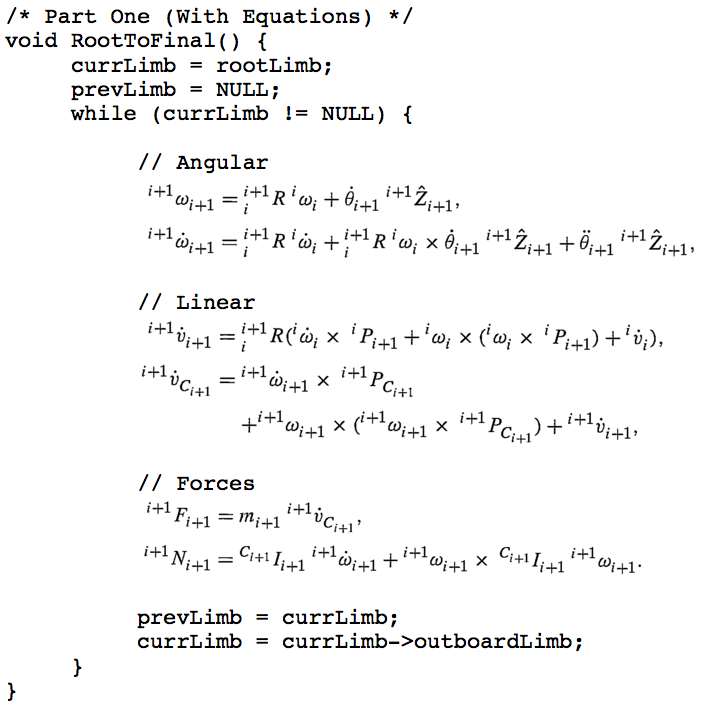
That’s the Newton-Euler method. Part One iterates forwards from the root limb. Part Two iterates backward from the final limb.
This a recursive method, but as you can see it does not need to be implemented recursively. It is called recursive because most computations rely on the value(s) from its inboard/outboard neighboring limb. However, it is useful to implement Inverse Dynamics recursively, when an inboard link is connected to multiple outboard links. In other words, a parent has multiple children, such as a common tree structure; otherwise, if it is just an arm, then you have more of a linked list structure without need for recursion.
Base Cases
Being that this is a recursive algorithm, we will need base cases for Part One and Part Two. For Part One, note that the root limb does not have an inboard neighboring limb; therefore, we can just treat any value (such as acceleration, angular velocity, or angular acceleration) for this non-existent limb as zero. However, if you’d like to include gravitational forces in your Inverse Dynamics algorithm, then you can set the acceleration for this non-existent limb to the gravitational constant of your choice (e.g., 9.81 m/s²).
For Part Two, note that the final limb does not have an outboard neighboring limb; therefore, we can just treat any value (such as force or torque) for this non-existent limb as zero. However, if the articulated body is not moving in free space, and it is in contact with the environment (e.g., the foot is on the ground, or the hand is carrying an object) then the contact forces and torques due to this contact can be set in this non-existent limb.
This has been an Implementation of Inverse Dynamics. If any jargon was confusing, please see an Overview of Inverse Kinematics or an Overview of Inverse Dynamics.
Read more about:
Featured BlogsAbout the Author(s)
You May Also Like


.jpeg?width=700&auto=webp&quality=80&disable=upscale)