Daily news, dev blogs, and stories from Game Developer straight to your inbox
Sponsored By
A deep technical dive into how the developers of the Just Cause series create their sprawling, seamless open worlds -- exploring all of the tricks and techniques they've developed so far.
May 16, 2013
21 Min Read

Sponsored by Avalance Studios
Author: by Linus Blomberg
Avalanche Studios was founded over ten years ago out of passion for open world gaming. But for me it actually started back in 1984 when playing Ian Bell's and David Braben's classic game Elite for the BBC Micro Model B. I was astonished by the way they could create a whole universe with 8000 unique planets that you could travel freely between, on a machine with just 32KB of memory and with a CPU running at 2 MHz. It was a completely different experience from all of the platform games and sidescrollers of the time. Mesmerizing.
Bedroom Space Cadets
My two brothers and I built a spaceship cockpit in a closet at home using old discarded machinery that our dad brought home for us from the university at which he was a professor. In the center sat the BBC and a joystick. Being the oldest brother, I was obviously the highest in rank, and in charge of the joystick, while my brothers were commanded to sit with a finger on the countermeasure keys, ready to EMP any incoming enemy missiles, or in worst case, activate the escape pod. Pressing too late often meant instant deportation to the vacuum of space -- the bedroom outside the closet. Luckily for me, that harsh penalty didn't kill their passion for open world games, and we eventually started experimenting in making our own.
We soon discovered fractals and how procedural techniques could be used to achieve experiences far greater than the typically perceived constraints of the hardware would allow -- just like Braben and Bell had done several years earlier. Living in the countryside in the north of Sweden, our interest became trying to replicate the landscape outside of our windows using these techniques. Many years (and much coding) later, a procedural landscape demo attracted the interest of an Eidos producer, and the Just Cause franchise was born.
Space and Beyond
Fundamental to the gameplay of the Just Cause series is the ability to move freely in an enormous world. Long draw distances are vital for the Just Cause experience, since the player's progression and motivation is much guided by visual input. We wanted the player to see things in the horizon and become interested to find out what hides behind that distant mountain range or on that remote island. The Avalanche Engine is developed from the ground up to cater to sandbox gameplay in huge open worlds with large draw distances.
There are many technologies required to achieve this, making it very difficult to retrofit open-world functionality to existing game engines. This article will describe one of those techniques, namely terrain rendering. More specifically it will describe how the terrain mesh is generated in the Just Cause games, and how we were able to draw a 32 by 32 kilometer world with full draw distance. It will describe our geo-morphing technique that made the long draw distance possible while at the same time eliminating level-of-detail "popping." It will also describe the resource management techniques and data compression required to efficiently stream and recreate the large amount of data required to generate the terrain meshes.
The goals for designing the terrain system in the Avalanche Engine were:
Memory efficiency. The original Just Cause was released on PlayStation 2, so we knew that we had to have a very tight memory representation to make a world of that size fit. Data compression and procedural techniques would be required.
High performance. There are a lot of things to render in an open world game so the terrain system cannot consume much of the available processing power. We knew that static vertex buffers would have to be used to achieve this, which ruled out some terrain rendering techniques.
High visual fidelity. Meant high resolution, no level-of-detail popping," large draw distance, etc. Again, especially considering the other two goals, procedural techniques would be crucial to accomplish this.
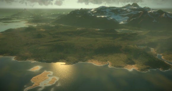 A typical Just Cause 2 vista
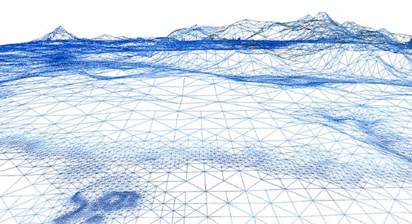
The same scene in wireframe. Note the increased resolution at the shorelines and other complex regions.
The Concept of Patches
Central to the landscape system in the Avalanche Engine is the concept of "patches." A patch, in this context, is a two-dimensional spatial container of data.
The size of a patch is always a power of two in both dimensions, its position is always a multiple of its size, and it's aligned to the world axes. The actual content of the patch is what defines its type. We use many different patch types in the engine, such as: stream patches, terrain patches, vegetation patches, etc. Each of these patch types has their specific use and purpose.
We call a collection of N*N patches of the same type a patch map. Usually a patch map is centered on the camera; meaning that if the camera moves, some patches in the patch map has to be destroyed, some has to be created, while some could remain valid.
There can also be hierarchies of patch maps, which we call patch systems. A patch system is a collection of patch maps of the same type, and where each patch map contains the same number of patches, but at a power-of-two size difference between them. This structure is used to represent different levels-of-detail of the same data. We say that patches overlapping in such a hierarchy have a parent/child relation; even though there is no actual connection between them other than that they cover the same area.
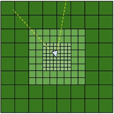
Figure 1: A patch system with three levels of patch maps centered on the camera
A central patch manager handles this administration and organization of patches. The patch manager doesn't know the type of the patch; it only sees the patch header and a blob of unknown data. Registered callbacks then deal with the type-specific actions, such as creation and destruction of the patches. This abstraction lets us more easily optimize the core patch handling which is helpful since there can be thousands of various patches in flight at the same time. The patch manager also does other generic work like testing patches against the view frustum, and dealing with memory management.
Data Pipeline
In the Avalanche Engine we use our proprietary editor called JustEdit (clever name, right?) for creating terrain. We don't worry too much about data size at this stage, since we can assume developer workstations with a decent amount of RAM. Therefore we use a raw height map format and a fixed resolution proxy mesh for the terrain in JustEdit, although we vary the resolution based on distance on a per patch basis for performance reasons. The terrain data in JustEdit is split up into editor patches on disc, which can be individually checked in and out from Perforce, so that we can have multiple artists working on the world at the same time.
The created data is then sent through a terrain compiler that optimizes the data format for the specified platform and outputs it as stream patches. This is a quite time-consuming process if done for the entire world, so it's an area subject to constant improvement. For our newest generation of tools we're actually using GPGPU processes to achieve live editing of local areas.
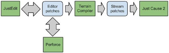
Figure 2: The data pipeline
Streaming
In the Just Cause series, there are no restriction on player movement (other than speed), so we had to organize the runtime data on disk in such a way that it can be efficiently streamed-in, regardless of the direction the player is moving. To achieve this, we split up the entire world in a regular grid of 64 by 64 cells. The world size is 32 by 32 kilometers, thus each cell covers 512 by 512 meters. We call each cell a stream patch, and they contain all the terrain data required to render and physically represent that area. We keep a patch map of 8 by 8 stream patches in memory, centered on the camera.
We wanted to be able to stream the data directly from optical disc, so it was really important to keep the number of seeks required to read the data to a minimum. However, we were in quite good shape when it came to the available disc size and we took advantage of this by actually storing the stream patches twice, both in x/z order and in z/x order. This way only one seek was ever needed to bring in a new row or column of eight stream patches. The maximum speed of travel was then restricted by the data transfer rate of the optical drive.
We ended up capping the maximum allowed speed of movement in the game at 512 meters per second in the horizontal direction, allowing an average data size for each stream patch of about 128kb. I say "average" because the data size for each patch was not fixed. What mattered was how much data there would be in any arbitrary location of 8 by 8 stream patches combined. This allowed us to have occasional patches that contained more than the average amount data, provided that they were surrounded by patches that contain less than the average data size. A pass in the terrain compiler iterate over the world to ensure that the memory budgets holds for every possible position.
The major terrain data categories stored in each stream patch are:
Terrain textures (materials and normal map)
Height map and material map (compressed to 16 bit/sample)
Terrain mesh data
The Terrain Textures
Other than the height map, we use three different types of textures for the rendering of the terrain in Just Cause 2:
Normal map (A8L8 format) - The normals of the terrain.
Material indices (ARGB4444 format) - The material type index.
Material weights (ARGB4444 format) - The weight of each material type.
The normal map texture is obviously used for shading -- nothing fancy there. The benefit of having the normals stored in a texture as opposed to in the vertices is that lighting becomes invariant of mesh resolution, which helps a lot when it comes to hide LODing. The material textures are used in the pixel shader to select and blend between various high-res material texture maps. The resolution of each of the textures is four meters/texel. This is quite a low texture resolution for terrain textures, but we use tiled detail textures that modulate these to achieve a higher final resolution. This is an example of where we use procedural techniques to improve the fidelity of the data.
I won't go into detail on the pixel shader in this article, but I can say that it is quite expensive and we spent a lot of time optimizing it. In fact, the frame rate is sometimes higher when there are a lot of trees on screen because they occlude the terrain, so we avoid the rendering of expensive terrain pixels. It's an interesting situation when drawing more actually improves performance!
The Height Map and Material Map
The source data resolution of the height map and material map in JustEdit is 4 meters per sample. The heights are stored as 16 bit values, and the material indices as 8 bits. In the PC version of Just Cause 2 we keep this format, but for Xbox 360 and the PlayStation 3 we compress the maps to 16 bits per sample in total. The compression a "lossy" scheme which takes 4 by 4 blocks of height and material samples and makes a number of simplifications of the data. The materials are simplified similarly to how the DXT texture format works, by using a table of four entries and 2 bit values for each sample used as lookup index into the table.
The height values are converted to a 3:6 floating-point format, where the 3 bit exponent is shared for 2 by 2 samples and each sample has a 6 bit mantissa. Using a floating-point format allowed us to have high precision in low frequency areas where it's typically the most needed. Packed into the block is also bounding data to optimize ray-casts. When sampling the data in run-time, a Catmull-Rom spline interpolation is performed on the unpacked samples, and high-resolution displacement maps controlled by the material map are added to the result. This way, high-fidelity height values are achieved with relatively little amount of data.
The height map can be sampled thousands of times per frame by the physics system, so it was crucial to achieve high performance on the sampling function. Therefore we use hand-tuned SIMD functions to unpack and sample the data. The VMX instruction set on Xbox 360 and PlayStation 3 is very powerful, and much of the magic was possible thanks to the versatile permute instruction. This instruction sadly doesn't exist on x86 architectures, which was one of the reasons why we were forced to have a different data representation on the PC.
The Terrain Mesh
So we've talked about stream patches, and how they have a fixed size of 512 by 512 meters. One can view stream patches as mere data containers that are streamed in to provide data upon request for other systems. Now, the terrain meshes are represented as a type of patches too. We call these terrain patches, and they basically contain a run-time generated vertex and index buffer representing the terrain in that area.
Terrain patches are organized as a patch system, i.e. a series of patch maps as described above. This is because there are several level-of-detail representations of the terrain mesh. There are twelve levels of terrain mesh detail in Just Cause 2. Each level consists of a patch map of 8 by 8 terrain patches, centered on the camera. The smallest level of the terrain patch maps covers an area of in total 64 by 64 meters, and at the largest level they cover an area of in total 256 by 256 kilometers. Note that this is much larger than the size of the game world; we have procedurally generated data outside of the game world to ensure that the visible distance is equal in a directions regardless of where you are on the map.
The concept of a level-of-detail pyramid of patches centered on the camera is similar to Geometry Clipmaps described by Hugues Hoppe and Frank Losasso, but we actually developed our system before that paper was published in 2004.
As the camera moves, new rows and columns of new terrain patches get constructed and old ones destroyed. Their data is either gathered from the stream patches, or from a global low-fidelity data representation, depending of the LOD level of the terrain patch.
Compile-Time Mesh Construction
Each terrain patch contains a mesh representing the terrain in that area. The resolution of this mesh is not uniform. The complexity of the landscape in the Just Cause series varies a lot from one location to another, so the number of triangles required to accurately represent the terrain varies greatly too -- therefore we didn't want a uniform terrain mesh resolution since that would mean a lot of unnecessary vertices, which would cost both vertex performance and memory. Also, small triangles are more expensive per pixel to render than large triangles, so we only want to use small triangles where they really make a visual difference. However, this is just for the graphical representation. For the underlying physical representation we used the fixed-size height maps described above.
There are a number of adaptive-resolution mesh schemes that take the viewpoint into consideration and adjust the resolution in real-time, like "real-time optimally adapting mesh" (ROAM), for instance. One problem with these is that they often introduce "popping" artifacts when changing the viewpoint, but more importantly that the vertex count can vary from frame to frame. Particularly on older hardware this is a very bad thing, since this would mean uploading new vertex data each frame.
With that in mind, one of our requirements was to have a fixed static vertex buffer for the life-time of the terrain patch. Basically this meant that we disregard the viewpoint and focus only on terrain complexity and distance from the camera for determining the resolution. For the terrain complexity part we went with an offline mesh construction solution, and for the distance part we used run-time selection of different LOD representations of the same data.
For the mesh data representation we came up with an adaptive scheme based on binary triangle trees. Although we came up with it independently, there are now several references to binary triangle trees on the internet, and one that closely matches our approach is described in a Gamasutra article from 2006 written by Chris Dallaire. A binary triangle tree is simply a tree in which a node defines a triangle and where two child nodes define a uniform subdivision of the parent triangle (see Figure 3). So to represent a rectangular patch of terrain, two triangle trees are needed. The rectangular patch is split along the diagonal, and the two resulting triangles are the root nodes of the two triangle trees.
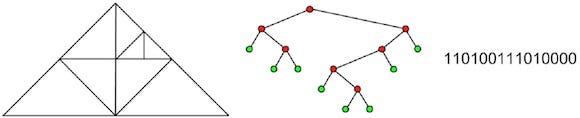
Figure 3: The same triangle tree in three different representations: Mesh, tree, and bit stream
An offline process in the terrain compiler generates these triangle trees by iterating over the terrain and measuring the topographic complexity. The more complex the terrain is, the deeper the resulting triangle trees are.
We also had heuristics other than complexity that influenced the tree depth. For instance, we always wanted maximum resolution along shorelines to get smooth looking island contours. The analysis works by starting with the root node and traversing over the height map within that triangle and summing up the differences between the triangle plane and height map samples. The tree is subdivided if this sum is above a specific threshold, and the process repeated for the child nodes. The resulting tree is stored as a bit-stream, where "1" indicates a node and "0" a leaf. This is an extremely compact representation of the terrain mesh. The X and Z positions are implicit by the tree structure, and the height value for each node is sampled from the height map in run time when the vertex buffers are generated.
In the original Just Cause game we actually stored the heights at each node in this structure too, and used planar interpolation to generate the height map values within a triangle. This was of course a very compact way to store the height map but we abandoned that in favor of simplicity with Just Cause 2, since we no longer supported PlayStation 2 and the original Xbox, and thus had higher memory budgets.
So, in essence, what's stored in each stream patch with regards to the terrain mesh is simply a bit-stream for each triangle tree. To make matter slightly more complex however, we actually do this process once for each patch size in the terrain patch maps. We basically store the terrain mesh twelve times over, with different resolutions, since there are twelve patch maps in the terrain patch system. The meshes that correspond to patch sizes that are smaller or equal to the stream patch size are stored in the stream patch and streamed in as part of the stream patch map, but the meshes that correspond to patch sizes larger than the stream patch are stored in an "always loaded" global repository.
Geomorphing
We now have 12 detail representations of the terrain mesh, organized in a terrain patch system. Obviously we don't want to draw them all on top of each other because that would just be, well, plain stupid, and not look very good. So we need to select between them in run-time based on the distance from the camera.
We also want some way of blending between the new selection and the previous selection to avoid a "popping" artifact when we switch between them. One solution would be to alpha blend between them in the pixelshader, over a specific blend region, but then there could be cracks visible in cases where the two meshes differ greatly.
The solution we ended up using was geomorphing. By geomorphing we mean gradually adjusting, or "morphing," the vertex positions of the higher resolution mesh to align with the lower resolution mesh, based on distance along a specific transition range. For this to work well without causing any cracks we need the morph target be exactly on an edge of the lower resolution mesh.
Note that this technique actually creates T-junctions along the edges of meshes of different LOD, but in practice this hasn't proved to be a visible problem.
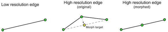
Figure 4: Morphing edges in the a high resolution mesh to align with a low resolution mesh
The triangle trees actually let us to this morphing very elegantly, without the need to store any additional information. Consider that the child terrain patch containing the higher resolution triangle tree partially cover the parent terrain patch containing the lower resolution triangle tree. If we traverse both the lower resolution tree and the higher resolution tree in parallel at the same time, then we can easily generate morph target information for the high resolution tree, based on the low resolution tree. This works conveniently since a higher resolution tree is always a superset of the lower resolution tree of the same area.

Figure 5: Traversing the lower resolution tree in parallel with the higher resolution tree identifies the morph targets
Vertex and Index Buffer Generation
Generating the vertex and index buffers is quite straightforward. When the terrain system receives a construction callback for a terrain patch from the patch manager, it queries the corresponding stream patch for the triangle tree data for that terrain patch. It then also asks the stream patch for the triangle tree data of the parent terrain patch. Now, since the parent terrain patch covers four times the area of the child patch, we must locate the branch of that tree that covers the same quadrant as the child patch. The two triangle trees are then traversed at the same time to build the vertex and index buffers, with the parent tree used to locate morph targets. This can be seen in the following pseudo code:
Figure 6: Pseudo code of the TraverseTree function that builds the vertex and index buffers of the terrain mesh. Click for larger version.
Partially Overlapping Patches
By definition, in a patch system some patches completely covered by child patches, some are not covered at all, and some are only partially covered. This is because each patch map is centered on the camera and 'moves' at different resolutions when the camera moves, since the size of the patches differs by a power of two between each patch map.
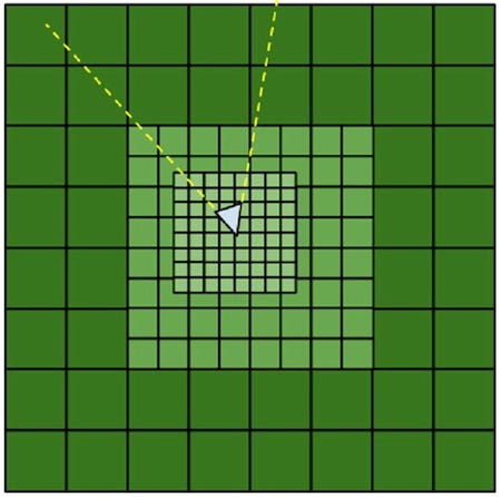 Figure 7: The patch maps 'moves' in different resolution due to the size difference of the patches
As a consequence of this, and as a final hurdle, we need to deal with the case of partially covered terrain patches so that we may draw quadrants of patches separately. This is achieved by organizing the index buffers of each patch into quadrants so that any quadrant can be drawn independently. A child coverage mask for each patch is provided by the patch system, indicating which quadrants (if any) are occluded by child patches.
Conclusion
The terrain system of the Avalanche Engine has proven to be very efficient on a wide range of hardware. It's the result of many years of development and iterations, and since the launch of Just Cause 2 there has been much further development that must be shrouded in secrecy for a little while longer. Creating technology that enables game designs that most sane designers never would dream of proposing is what drives me, and much of the inspiration goes all the way back to the childhood spaceship in the closet.
Who back in 1984 would pitch a game idea that featured 8,000 unique planets where you could choose to become a trader, a pirate, or a bounty hunter, when most games were about jumping on platforms avoiding monsters? Well Braben and Bell did, because they possessed the spells of creative technology. With so many new markets emerging and new generations of hardware on the horizon, these are exiting times if you're into creating technology that people reference in articles 30 years later.
You May Also Like