Daily news, dev blogs, and stories from Game Developer straight to your inbox
Sponsored By
Featured Blog | This community-written post highlights the best of what the game industry has to offer. Read more like it on the Game Developer Blogs.
This paper describes some tech details in Spin Tires, a game about a big truck driving through mud/water, crushing trees and everything else on its path.
22 Min Read

Rendering and simulation in offroad driving game
This paper describes some tech details in Spin Tires, a game about a big truck driving through mud/water, crushing trees and everything else on its path.
You can download playable demo (100 Mb) and see screenshots/videos at official site or at Oovee site.
All code samples are either given in C++ language, or DirectX HLSL. In code samples, left-handed DirectX coordinate space is assumed.

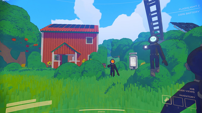
Figure 1. Spin Tires - daytime lighting with direct sun
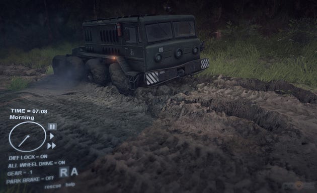 Figure 2. Evening time transition
1. Rendering
High-end for Spin Tires is GeForce GTX 260 which is at best considered mid-end in the industry. Lets say Spin Tires is goodlooking, so there are several unique algorithms that make it work fast, all based on a fact that a driving game like that is essentially a 2d game. Spin Tires basically consists of a heightmap and trees!
1.a. Daylight with no sun
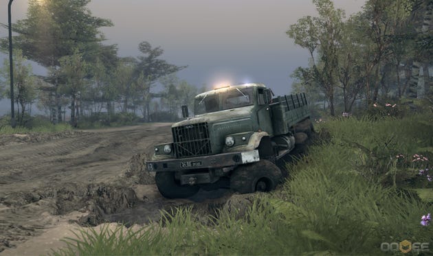
Figure 3. Spin Tires daytime lighting without sun
Fun facts for scene at fig.3:
220 meters visibility distance (below average for 3d game)
3340 trees (below average for Spin Tires)
420 DIPs (a lot of instancing), 50 various pixel/vertex shaders (DirectX effects system used)
*DIP - "draw indexed primitive", a basic operation of submitting draw command to GPU, amount of DIPs defines how much CPU time does rendering system use.280000 faces, opaque color pass overdraw: 1.5
No Z prepass!
For GTX 260, GPU opaque color pass time: 7-8ms (resolution 1450x860)
Z prepass time: 4-5ms, consecutive color pass: 5-8ms, plus CPU time required to draw scene twice.
So for scene where hi-z doesnt work well, z prepass does not give performance gain (its even worse on slower videocards like Intel Graphics).
Consequences of not having depth texture in color pass would be discussed later.Shader model 3.0 (DirectX 9)
Average shader instructions count: vertex 140, pixel 90.
Grass shader (most fillrate heavy): vertex 189, pixel 46 - per-vertex lighting
Heaviest shader: vertex 202, pixel 207 - terrain surface with parallax (tessellated near camera, uses per-vertex lighting)
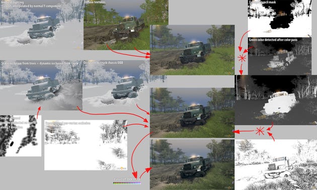
Figure 4. Daytime lighting without sun scheme
Points of interest:
Per-vertex fog
Per-vertex DOF factor outputted into A channel
Static occlusion from trees is used to attenuate ground and bottom parts of trees using local vertex position Y component
Math to compute occlusion from truck chassis OBB is the same as used to deflect grass under truck:
static const float _OCCL_FALLOFF = .4f;
static const float _OCCL_HEIGHT_FALLOFF = .3f;
// XZ center of OBB
shared float2 g_vOcclCenter = float2(0, 0);
// g_vOcclData[0].xy = XZ components of OBB local "X direction"
// g_vOcclData[0].z = local space OBB size along "X direction"
// g_vOcclData[1].xy = XZ components of OBB local "Z direction"
// g_vOcclData[1].z = local space OBB size along "Z direction"
shared float3 g_vOcclData[2] = { float3(0, 0, 0), float3(0, 0, 0) };
// world-space heights of each of bottom OBB corners
shared float4 g_vOcclHeight = float4(0, 0, 0, 0);
float GetOBBOcclusion(in float3 vertexPos) {
float deflectFactor = 1.f;
float isInside = 1.f;
// Along X, then Z
float2 heights;
float heightAt;
[unroll]
for (int i = 0; i < 2; i++) {
const float3 data = g_vOcclData[i];
float deflectorSize = data.z;
float distPlane = dot(vertexPos.xz - g_vOcclCenter, data.xy) + deflectorSize * .5f;
float distSecondPlane = deflectorSize - distPlane;
if (i == 0) {
heights = lerp(g_vOcclHeight.xy, g_vOcclHeight.zw, distPlane / deflectorSize);
} else {
heightAt = lerp(heights.x, heights.y, distPlane / deflectorSize);
// just some shrinking of the occl volume near top
distPlane -= saturate(vertexPos.y - (heightAt - 1.f)) * .4f;
distSecondPlane -= saturate(vertexPos.y - (heightAt - 1.f)) * .4f;
}
// Need a smooth transition
isInside *= saturate(1.f + (distPlane - _OCCL_FALLOFF) / _OCCL_FALLOFF);
isInside *= saturate(1.f + (distSecondPlane - _OCCL_FALLOFF) / _OCCL_FALLOFF);
}
float heightFactor = saturate((vertexPos.y - heightAt) / _OCCL_HEIGHT_FALLOFF);
isInside *= 1.f - heightFactor;
return 1.f - isInside;
}SSAO is computed after opaque color pass - so it is applied on top of lighting (but before transparent color pass).
The idea is, we dont want to have too much SSAO on grass and trees leaves, so by detecting green color (typical foliage color) and multiplying it by stencil mask, we approximate material AO intensity.
This tricky approach works surprisingly well - and is very scalable. If you dont have Z prepass, you need to use IntZ texture to readback depth buffer - but that is not always supported!
Alternatively it is possible to write out material AO intensity to alpha channel - but it is reserved for DOF factor in Spin Tires, which is considered more important effect and it works wihout IntZ support.Level in Spin Tires is divided into rectangular 16x16 (meters) blocks - called terrain blocks.
Each block contains list of trees, precomputed lightmaps, and a block map - ARGB8888 texture:
B - muddiness factor. Muddy areas are marked with darker/yellowish tint
G - material factor. Each block can only mix 2 diffuse textures
R - heightmap value. Block also contains float-value heights for 4 corners of the block, so BYTE is sufficient to store height
A - extruded flag. Extruded vertices are simply pushed down (along world "Y" direction) and mud (high-res terrain with different shader) is rendered inplace
Block can also contain "overlay" (a road) - in which case it uses additional diffuse and additional per-block ARGB8888 texture:
BG - packed "overlay" UV texture coordinates
R - "overlay" transparency
A - unused (no 3-channel texture available unforunately, and Spin Tires hits limit of 4 vertex samplers)
Each block selects its LOD, and uses one of pre-generated meshes to render itself.
1.b. Daylight with sun
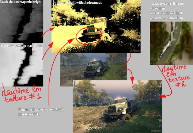
Figure 5. Most tricky here are static shadowmap min/max textures - generated at level export time by special shader (entirely GPU algorithm) - usage described below
A traditional PCF shadowmap is generated for sun with only truck rendered to it - this allows to avoid cascaded shadowmaps.
Shadows from static objects (trees) is encoded into single A8L8 texture. The texture stores min height ("Y" component) of "shadowed" volume and max height.
Big assumption here is that at any given XZ world position shadow can be represented as a continuous volume - which is of course not the case for complex objects like bridges. But it "works" for Spin Tires and is pretty cheap, here is the code to decode static shadowmap:
static const float MAX_LIGHT_HEIGHT = 64.f;
const float shadowStartY = (1.f - lightMap2.r) * MAX_LIGHT_HEIGHT;
const float shadowEndY = lightMap2.a * MAX_LIGHT_HEIGHT;
const float shadowEndDelta = 3.f;
float smAtten = 1.f - saturate((worldPos.y - shadowStartY) / .5f);
smAtten = max(smAtten, 1.f - saturate((shadowEndY - worldPos.y) / shadowEndDelta));
It also generates soft looking shadows, which when blended with sharp PCF shadowmap gives nice look.
Another big problem tho is that maximum encoded height is 64 (meters) - and precision is awfull. It can be fixed by moving to FP texture.
1.c. Nighttime
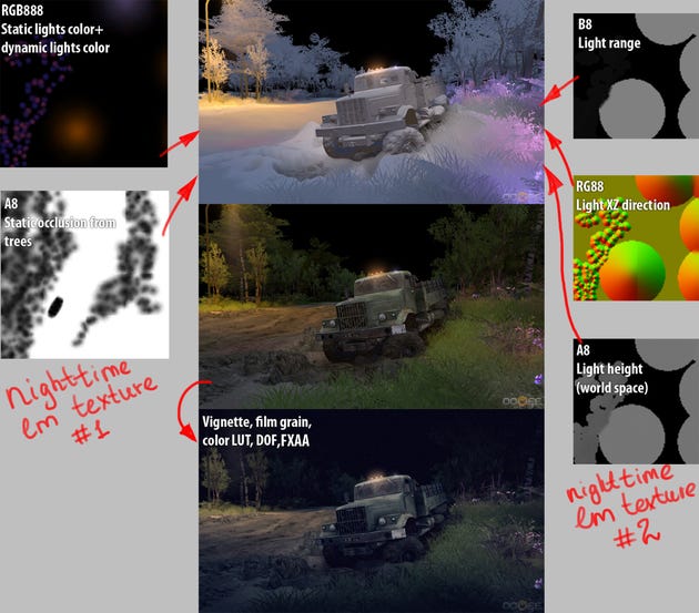
Figure 6. Night mode in Spin Tires
No fog used at fig.6 (night in Spin Tires was supposed to be spooky) - instead ambient lighting is faded in the distance (as well as lightmap lighting) - blacking out scene background.
Above the truck, a "godlight" is installed to constantly illuminate area around truck.
When truck moves into area of static light, ambient lighting changes color to match it.
Nighttime is different from day - and it uses different set of tricks, all again based on the fact that Spin Tires is 2d heightmap-based game.
Night lighting uses 2 textures (as well as day lighting - but different ones), those textures are represented by render targets containing precomputed textures only for visible terrain blocks.
All lighting except head lights is encoded into 2 ARGB8888 textures. Here is the code that restores averaged light parameters illuminating given world XZ position (~40-50 instructions)
float UnpackLightHeight(in float h) {
return UnpackHeight(h, 0, MAX_LIGHT_HEIGHT);
}
float3 UnpackLightColor(in float3 rgb) {
return rgb * MAX_LIGHT_COLOR_CHANNEL_VALUE;
}
float UnpackLightRange(in float r) {
return r * MAX_LIGHT_RADIUS;
}
float3 UnpackXYZDirection(in float2 xzDir, in float heightOffset) {
static const float yUnpackEmpiric = 1.5f;
float yScale = heightOffset / yUnpackEmpiric;
float2 xzDirSigned = (xzDir - .5f) * 2.f;
float yComponent = sqrt( 1 - dot(xzDirSigned, xzDirSigned) ) * yScale;
return normalize( float3(xzDirSigned.x, yComponent, xzDirSigned.y) );
}
void AddTerrainPackedLighting(inout LIGHTING_DESC lighting, in SURFACE_DESC surface, in float4 lightMap1, in float4 lightMap2) {
// lightMap1: RGB - light color, A - light occlusion (used for both direct and ambient lighting)
// lightMap2: RG - xz dir to light, B - light height, A - light atten range
float3 lightColor = UnpackLightColor(lightMap1.rgb) * g_fLightingMode;
float lightHeight = UnpackLightHeight(lightMap2.b);
float attenRange = UnpackLightRange(lightMap2.a);
// Attenuation is computed with regards to height offset, XZ offset is already embeded to lightColor
float heightOffset = lightHeight - surface.worldPos.y;
float3 dirToLight = UnpackXYZDirection(lightMap2.rg, heightOffset);
float lambertAtten = GetLambertAtten(-dirToLight, surface.worldNormal, g_fBacksideLighting);
// 2.0 multiplier makes distAtten 1.0 for < attenRange * 0.5 then linearly fades to 0 by attenRange
float attenParam = heightOffset / attenRange;
float distAtten = saturate( (1.f - abs(attenParam)) * 2.f );
// the same as : saturate( 1.0 + (1.0 - abs(heightOffset) / (attenRange / 2.0) );
lighting.diffuse += lightColor * lambertAtten * distAtten;
#if defined(SPECULAR)
float phongSpecular = GetSpecular(-dirToLight, surface);
lighting.specular += lightColor * phongSpecular * distAtten;
#endif
}
And it basically looks "satisfying". Lightmaps for the level are generated at export time - but dynamic lights can be blended with static lightmaps using special shader (fig.7).
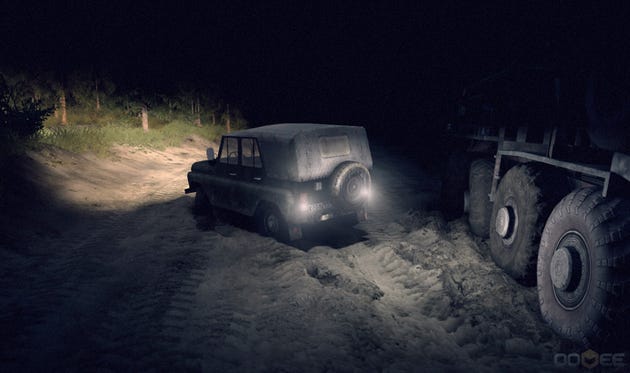
Figure 7. Reverse lights are dynamic, but they are "blended" with static lightmaps and do not incur any overhead!
The only "true" light in Spin Tires is head light, for which quality is critical.
Notice shadowmap under the jeep. It is a fake! Shadowmap is generated with default direction (along world -Y) - although it can actually changes its direction for designated "big" lights like street lights.
Fun fact: head light can be turned off, so originally it used to be extra shader combination, but to reduce number of shaders (almost twice) it is now always computed, but the conditional "if" makes the performance hit minimal when head light is actually disabled.
Fun fact: default lambert attenuation for head light looked bad without shadowmap, so the tweaked formula is
atten = lerp(NdotL, 1.f, .25f);
2. Simulation
2.a. Vehicle
Spin Tires uses Havok Physics. Havok Physics provides interface to create vehicles, and would handle all simulation (and even most of user input/camera following). You can create raycast vehicle - in which case, while simulating, Havok would shoot ray from a position of hardpoint of a wheel to determine its position, or linear cast vehicle, in which case Havok would use wheel geometry to determine collision points with ground.
Neither of them work good when you drive over dynamic rigid bodies - because wheel isnt an actual body in simulation, so it responds to collisions incorrectly (and incorrectly affects other bodies).
Another problem is that with Havok vehicle, all wheels are attached to single ridig body (the chassis). But chassis of big truck can twist a lot (not to mention exotic trucks) - so if you want to chassis to be multiple bodies+constraint, at best you would have to create multiple vehicles.
So Spin Tires dont use any of Havok vehicle interfaces - it creates a vehicle as a set of bodies linked by constraints.
And get two problems:
- stability at high speed
This is the reason Havok uses raycast/linearcast vehicles; rigid bodies dont get simulated correctly when they are moving fast, and if vehicle wheels dont get simulated correctly, vehicle dynamics breaks up completely. Unfortunately, thats what happens in SpinTires - so I limited cap speed for vehicles.
Possible solution would be to gradually reduce the radius of the wheel when it starts moving fast (either linear of angular velocity) - and compute the forces applied to chassis on your own (reimplementing parts of Havok raycast Havok vehicle).
- rotating the wheels in response to user input
Applying force to a wheel looks like this:
hkVector4 wheelTorque;
wheelTorque.setMul4( wheelForceMultiplier * PHYSICS_TIMESTEP, wheelAxle );
pWheelBody->;applyAngularImpulse( wheelTorque );
Looks easy, but wheelForceMultiplier cant be simply proportional to user input (joystick position). If it is, and lets say wheelTorque is big enough to overcome friction - once static friction turns into dynamic friction, wheel angular velocity would exponentially increase and it will become unstable. Even worse if a wheel hang in air - it would go ballistic immediately. So you have to use feedback (check how wheel angular velocity changes before applying torque).
Not going into details - in Spin Tires its one hack ontop of another, but having established feedback, implementing locking/unlocking differentials is pretty easy and is more or less "physically correct".
Wheels
Physical simulation for wheels use Havok Softness Modifier. To make appearance of soft body, a single (average) contact point is passed to vertex shader in local space, and following code offsets vertices:
float3 GetSoftnessOffset(in float3 localPos, in CUSTOM_BASE_INPUT cbi)
{
const float halfWidth = g_wheelParams.x;
const float radius = g_wheelParams.y;
const float contactOffsetZ = g_softParams.y;
const float contactAngle = g_softParams.z;
const float contactDepth = g_softParams.w;
// Upack COLOR
float4 vDir = UnpackNormal4(cbi.vDir);
vDir.z *= TANGENTSPACE_BINORMAL_SIGN;
float a0 = .6f * (contactDepth + .1f) / radius;
float a1 = 1.0f * (contactDepth + .1f) / radius;
float a = abs(vDir.a - contactAngle);
if (a > 1.f) {
a = 2.f - a;
}
// Radial offset
{
float factor = lerp(-0.8f, 1.0f, pow(saturate(a/a0),2));
factor *= lerp(1.f, 0.f, saturate((a - a0)/(a1 - a0)));
vDir.xy = vDir.xy * factor * contactDepth;
}
// Perpendicular offset
{
float factor = 1.f - saturate(a / a1 * .8f);
float zOffset = vDir.z * factor * contactDepth;
vDir.z = clamp(zOffset, -halfWidth * .4f, halfWidth * .4f) * 2.f;
}
float dZ = abs(localPos.z - contactOffsetZ) / halfWidth;
dZ = saturate(1.8f - dZ);
vDir *= dZ;
return vDir.xyz;
}
Additonally, per-vertex offset noise is applied when wheel gets dirty to make appearance of mud sticking to wheel:
const float mudCoef = g_wheelParams.w;
float seed = localPos.x * 7.371f + localPos.z * 5.913f + localPos.y * 3.598f;
localPos *= 1.f + lerp(0.f, abs(fmod(seed, .06f)) - 0.02f, mudCoef);
2.b. Water
Havok provides a lot of usefull interfaces, so to create water (or mud, in SpinTires they use the same algorithm), you need to detect bodies that are inside volume of water (using so-called Havok-phantom), compute forces and apply them!
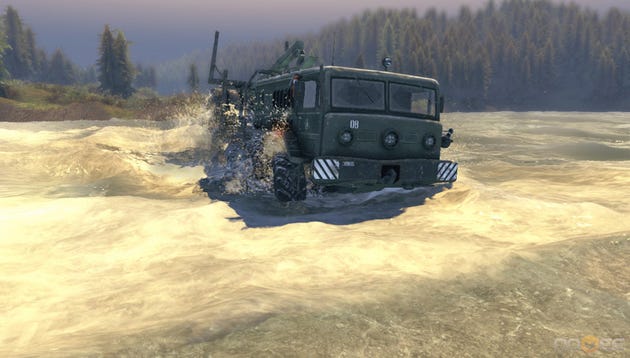
Figure 8. Dynamic water in Spin Tires
Water rendering pipeline:
Draw opaque color pass
Draw underwater particles
Apply SSAO
Copy backbuffer into a texture to be used for water refraction
Draw water surface (with z-write), use depth buffer for caustics, refraction, water transparency
Draw transparent stuff, apply color LUT, finish rendering
Water is currently represented by rivers, which are splines with widths. River is subdivided into blocks, each of those is rendered by rectangular mesh with given LOD. Vertex shader transforms vertices along river spline.
Decision to represent water by rivers was motivated by requirement to have water flow - but it turns out to be a poor one... Having a spline that defines a river restricts form of water.
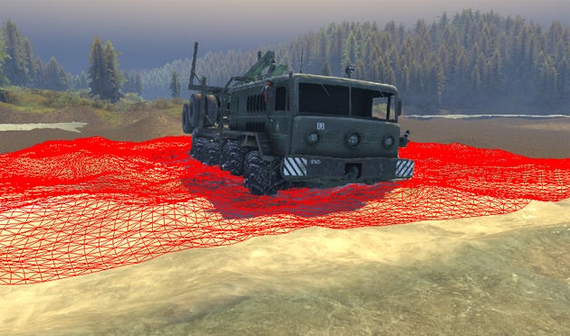
Figure 9. A single water DIP: block with given LOD for one of the rivers.
Water uses extremely simple simulation algorithm, it uses single ARGB8888 texture:
R - water opacity (static, precomputed)
GB - dynamic flow direction
A - dynamic foam
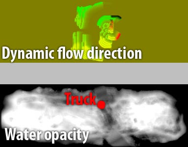
Figure 10. Per-river render target for dynamic water simulation (used as vertex texture in rendering)
Algorithm looks like this:
0. compute static water opacity (R channel)
1. draw water distorters to render target (GB channels) - simple quads with setting up flow direction outwards from distorter center.
2. do simulation, using render target from previous frame (so actually need to have 2 render targets - and swap them)
3. goto 1.
Simulation code (pixel shader):
#define RIVER_MAP_OPACITY(x) x.r
#define RIVER_MAP_SPEED(x) x.gb
#define RIVER_MAP_FOAM(x) x.a
static const float4 RIVER_MAP_DEFAULT = float4(.5f, .50196f, .50196f, .1f);
float2 GetRiverFlow(in float4 riverMap, out float flowSpeed) {
float2 d = (RIVER_MAP_SPEED(riverMap) - .50196f) * 2.f;
flowSpeed = length(d);
return d;
}
float4 updateMapPS(in float2 t : TEXCOORD0) : COLOR0
{
#ifdef NO_VFETCH
return RIVER_MAP_DEFAULT;
#endif
const float unitWeight = 1.f;
const float diagonalWeight = 0.707f;
const float2 txl = g_vRiverMapSizeInv;
const float3 offsets[8] = {
float3(-txl.x, -txl.y, diagonalWeight),
float3(0 , -txl.y, unitWeight),
float3(+txl.x, -txl.y, diagonalWeight),
float3(-txl.x, 0 , unitWeight),
float3(+txl.x, 0 , unitWeight),
float3(-txl.x, +txl.y, diagonalWeight),
float3(0 , +txl.y, unitWeight),
float3(+txl.x, +txl.y, diagonalWeight),
};
float4 riverMap = tex2D( g_samRiverMap, t );
static const float dampCoef = 0.8f;
static const float traverseCoef = 0.9f;
static const float2 globalFlow = float2(-1.f, 0);
float foamSumm = 0;
// Update flow
{
float flowSpeed;
float2 flowDir = GetRiverFlow(riverMap, flowSpeed);
flowDir = normalize(flowDir + globalFlow * g_fFlow * .25f) * flowSpeed;
for (int i = 0; i < 8; i++) {
float4 neighbor = tex2D( g_samRiverMap, t + offsets[i].xy );
foamSumm += RIVER_MAP_FOAM(neighbor);
float s;
float2 d = GetRiverFlow(neighbor, s);
float dp = dot(normalize(d), -normalize(offsets[i].xy));
flowDir += d * saturate((s - flowSpeed) / .25f - .5f) * saturate(dp) *
offsets[i].z * traverseCoef;
}
flowDir *= dampCoef;
if (abs(flowDir.x) <= .05f) {
flowDir.x = 0;
}
if (abs(flowDir.y) <= .05f) {
flowDir.y = 0;
}
// fade quickly at low opacity
float waterOpacity = RIVER_MAP_OPACITY(riverMap);
flowDir *= saturate(waterOpacity * 8.f);
RIVER_MAP_SPEED(riverMap) = flowDir / 2.f + .50196f;
}
// Update foam
{
float4 riverFlow = tex2D( g_samRiverMap, t - globalFlow * txl );
float resultFoam = lerp(
RIVER_MAP_FOAM(riverMap) = RIVER_MAP_FOAM(riverMap) * .49f + foamSumm / 8.f * .5f,
lerp(RIVER_MAP_FOAM(riverMap), RIVER_MAP_FOAM(riverFlow), .8f) * .9f, g_fFlow);
RIVER_MAP_FOAM(riverMap) = resultFoam;
}
return riverMap;
}
2.c. Mud
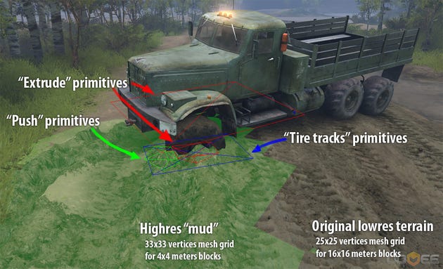
Figure 11. Mud in Spin Tires
Mud is generated only where truck deforms terrain. As already stated, terrain is subdivided into blocks.
Each block has associated ARGB8888 texture, and one of the channels of that texture defines what vertices of original terrain to be shifted down, and high-res heightmap mesh to be rendered inplace.
The deformations of the mud itself are stored in another ARGB8888 texture (per-terrain block):
R - height offset
G - unused (plans to use it for wetness mask)
B - tire tracks (simply a mask for different diffuse texture)
A - mask replicating texture of original terrain - positions where terrain is actually deformed and mud should be visible
During simulation, for objects that should penetrate mud, "extrude" primitives are built and rendered into the deformations texture R channel with D3DBLENDOP_MIN blending mode.
In front of wheels, "push" primitives are built and rendered with D3DBLENDOP_MAX (making a small hill in front of objects moving in mud).
Where mud is deformed, "tire tracks" primitives are rendered into B channel.
The defromations texture itself is thus entirely GPU-resident (not used for physical simulation)
Note: mesh grids for terrain rendering are 25x25 (33x33 for mud) so successive mesh LODs match each other.
3. Tools for terrain creation
It so happened, there is a home-made terrain editor in Spin Tires (C++ MFC, shares engine with the game).
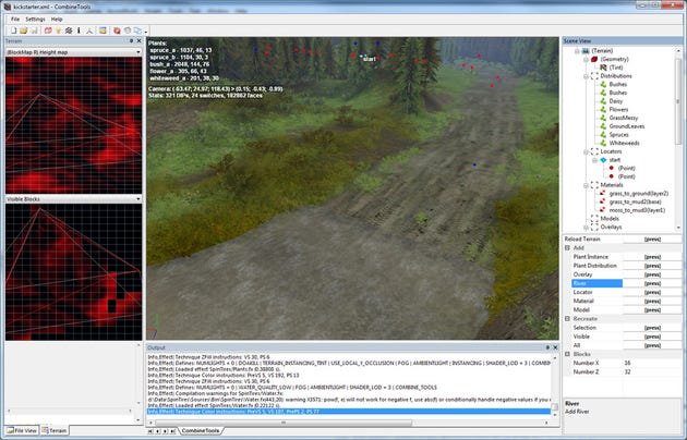
Figure 12. Terrain editor
Source files for Spin Tires level is XML file (storing positions for roads curves, rivers, level objects, etc.) and a set of top-projected textures (trees distribution textures, heightmap, material maps, etc.)
Terrain editor converts the level (it can convert only subset of terrain blocks) - computes lightmaps, performs various export-time optimizations.
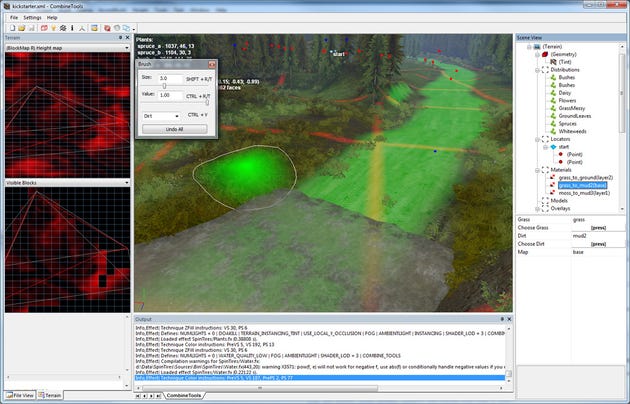
Figure 13. Terrain editor contains functionality to paint textures used to build the level (they can alternatively be painted on Photoshop)
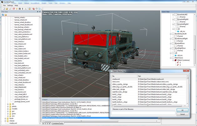
Figure 14. Terrain editor also views mesh assets - which use DirectX X file format (there are not many viewers for that format)
Alt-Shift-O (aka Visual Assist) is a great helper in any tool!
Given Spin Tires experience, I still cant say if designing own game editor is a good idea. On one hand, it allows to implement features very fast and not worry about "not seeing what you get".
On another hand, making a user friendly tool is a big deal, so if you want artists to work effectively, give them raw Maya/3dsMax/Photoshop/Zbrush.
So basically decision have to be made for each individual project.
4. Few more things that might be interesting
Full number of shaders in Spin Tires: 1200, collected by flying through scene - and of course some combinations are always missed what leads to retail-time stalls.
Middleware used in Spin Tires: Havok Physics, LUA, PhysFS, pugiXML, zLib, DirectX samples' DXUT.
Multithreading only used for Havok Physics - which does not give an obvious performance boost by simple observations.
In-game GPU timers implemented. Nested CPU timers implemented - using Havok Physics SDK!
99% of performance problems can be solved with in-game timers, and very efficiently.
In-game triggers are life savers. In Spin Tires, basically each keyboard key either triggers event or changes game state (analog to debug console). For instance, to freeze the game processing (while still maintaining free camera movement), need to press CTRL-C (in debug game build only).
Having Spin Tires optimized like it is allows to dream about porting it to X360/PS3 - the only problem might be fillrate when dealing with vast forest arrays.
Relying on DirectX11 would prevent it. Some Spin Tires users even complain about not able to run Spin Tires on videocard not supporting shader model 3.0.
But its hard to say how switching to DirectX11 would really affect userbase at this point.
Trees in Spin Tires are rendered using harware instancing. In area around truck, each tree has Havok Phantom - which detects collisions with tree AABB. When collided, tree instance is replaced with skinned model.
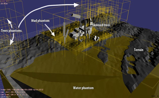
Figure 15. Physics world as seen from Havok Visual Debugger
In order to use DirectX effects system efficiently, a lot of additional coding has to be done... the final look for the interface that defines "handles" to effects parameters (constants) looks like this:
// EH for Effect Handle
enum {
EH_TERRAIN_TX_BLOCK_MAP = _EH_TCOMMON_LAST,
EH_TERRAIN_TX_OVERLAY_MAP,
EH_TERRAIN_TX_OVERLAY,
EH_TERRAIN_TX_OVERLAY_HM,
EH_TERRAIN_V_OVERLAY_TC_DATA,
EH_TERRAIN_V_BLOCK_POS_DATA,
EH_TERRAIN_V_CORNER_HEIGHTS,
EH_TERRAIN_V_PARALLAX_SCALE,
EH_TERRAIN_TX_GRASS,
EH_TERRAIN_TX_DIRT,
_EH_TERRAIN_LAST
};
DEFINE_EFFECT_FILE_HANDLES("SpinTires/Terrain.fx", _EH_TCOMMON_LAST, _EH_TERRAIN_LAST,
g_txBlockMap \
g_txOverlayMap \
g_txOverlay \
g_txOverlayHM \
g_vOverlayTcData \
g_vBlockPosData \
g_vCornerHeights \
g_vParallaxScale \
g_txGrass \
g_txDirt);
And setting up a constant looks like this:
pEffect->SetTexture(EH_TERRAIN_TX_GRASS, _RESOURCE_TEXTURE(material.grass.pTex));
Thats it, best regards and thanks for reading!
Read more about:
Featured BlogsAbout the Author(s)
You May Also Like