Daily news, dev blogs, and stories from Game Developer straight to your inbox
Sponsored By
Featured Blog | This community-written post highlights the best of what the game industry has to offer. Read more like it on the Game Developer Blogs.
Here we present technical details behind rendering of Mud and Water in Spintires:MudRunner, a driving simulation game, developed by Saber Interactive and published by Focus Home Interactive on Xbox One, PlayStation 4 and PC (Steam).
16 Min Read

Here we present technical details behind rendering of Mud and Water in Spintires:MudRunner, a driving simulation game, developed by Saber Interactive and published by Focus Home Interactive on Xbox One, PlayStation 4 and PC (Steam).
Spintires:MudRunner doesn't use third-party game engine. The author of this blog post is lead developer of the game.
THE MUD OF MUDRUNNER
Let’s take a game screenshot and decompose it.
How about this one?
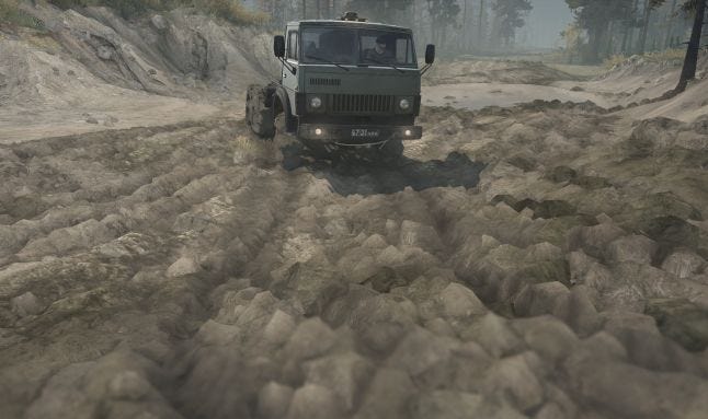
Let’s start by disabling post-processing: SSAO (ambient shadows), FXAA (softens object edges), DOF (blurs foreground), Sharpen Effect and Color Correction:
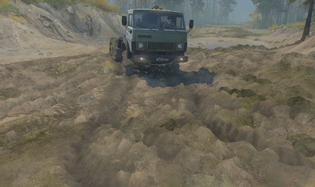
Now let’s take away all the layers in the reverse order they are applied when the game renders a frame.
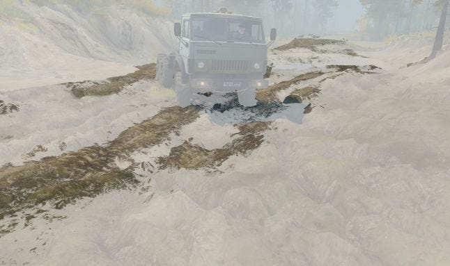
1. Terrain Mud Decals (will get back to it later)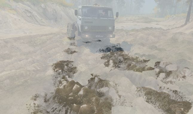
2. Wheel Tracks (will get back to it later)
3. Mud Particles.
Those objects float on top of the mud and are affected by vehicle wheels (can stick to them even), they only act as decoration and don’t affect the physics. Mud particles are simulated by the CPU in a separate thread. A lockless synchronization technique makes that whole effect very performance-friendly.
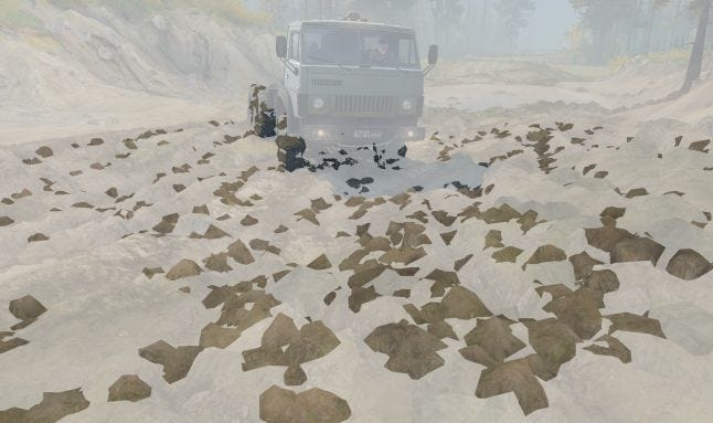
4. Mud Chunks
These are bigger chunks of mud, each is a full-fledged rigid body so they interact with the physics world properly and they even break into smaller chunks, when vehicles drive over.
They are maintained by the same systems that simulate and render all other plant types in the game. (A “plant” is an object that is scattered over the terrain in large quantities, like rocks or trees.)
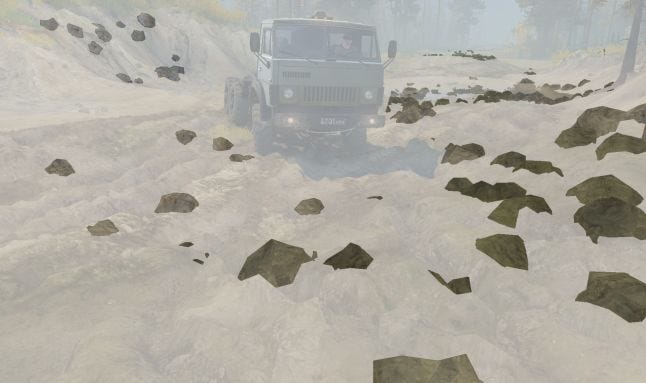
5. Road Overlays with Parallax Effect.
Roads, that map author places within Level Editor, are then baked into a special data that game uses to draw them efficiently. They are not actually rendered as a separate layer and are embedded into terrain shaders.
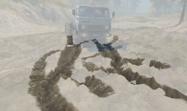
Now we are left with the mud itself, which is a simple heightfield (essentially a 2d mesh):
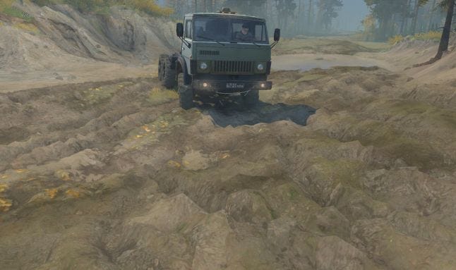
Have a look at its wireframe: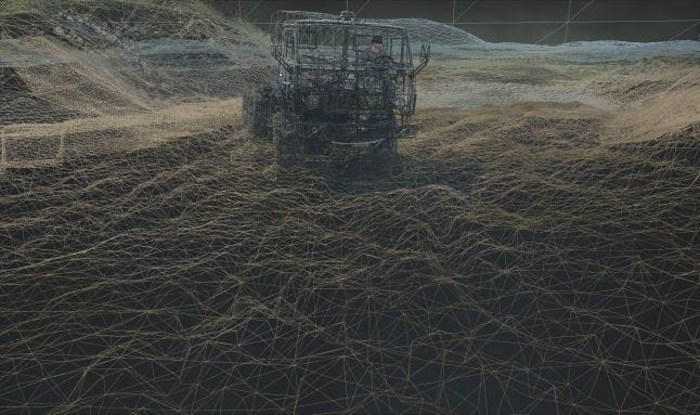
But most of the game level terrain is actually rendered at lower resolution. So if vehicles have not deformed terrain, its wireframe would have looked like this: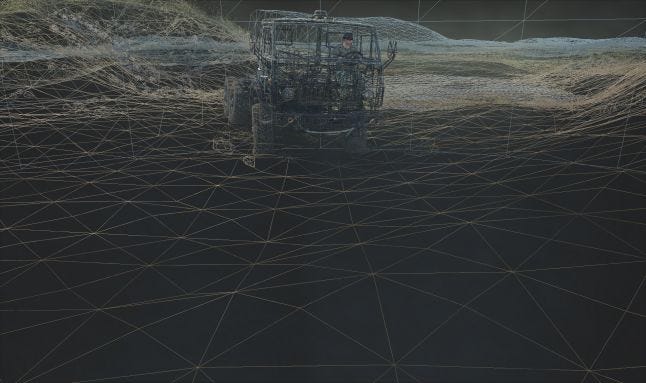
Now let’s have a closer look at each layer…
MUD HEIGHTFIELD
Game levels in MudRunner can be up to 1km x 1km in size. They are subdivided into a grid of 16m x 16m blocks. Each block contains a list of plants (trees, rocks, etc.), base terrain data, mud data (optional), and other data. Game only draws those blocks that are inside camera “frustum”. Only those blocks that are near the truck that player is driving are “active”. Game only performs plants physics simulation, mud simulation and water simulation for “active” blocks.
The mud simulation consists of mud-vehicle physics processing (performed by CPU) and rendering of the mud (performed by GPU). For a number of reasons (CPU and GPU are out of sync on PC, high detalization required for rendering is not required for physics, etc..), those two tasks operate on completely different sets of data. We won’t go into details of physics here, but in short, there is no rocket science involved, but it’s not something Havok (physics engine in MudRunner) can do out of the box.
In order to draw the mud, vertex shader takes in a simple 2d grid of vertices, then fetches two A8R8G8B8 textures that look like this:

Texture 1. 25x25 in size for each block, is used for rendering both low-res base terrain and the high-res mud.
R (red) channel – packed height (elevation). It is unpacked into real-world height with a bit of math.
G (green) channel – grass/dirt materials mix factor. Currently, each block can only mix 2 materials.
B (blue) channel – “tint” factor. Tint adds some color variation to the environment, and illustrates physics properties (“tinted” terrain is softer).
A (alpha) channel – marks portions of base terrain that are substituted by the mud, it’s the only channel that is dynamically updated as vehicles deform terrain.

Texture 2. 128x128 in size, is only allocated for blocks with mud.
R (red) channel – “mud height”, is relative to elevation of base terrain. It gets unpacked into a floating point value with a simple multiplication.
GB (green, blue) channels – used for “mud offset” effect (the mud slides away from vehicles wheels as they move).
A (alpha) channel – “mud tracks”, a blending factor of terrain shader into mud shader, In combination with A channel of Texture 1 that makes mud transition into terrain unnoticeable.
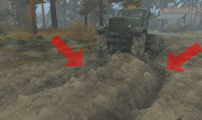
The visual part of mud simulation boils down to properly updating Texture 2:
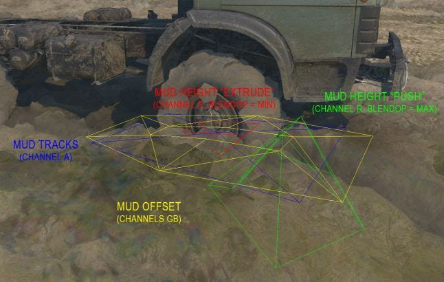
With a knowledge of wheels and chassis positions, their size and velocities, and their current mud penetration depth, CPU forms various “primitives” and draws the into a “Texture 2” (RT – render target), which is then read back by GPU. That is pure empirics and have very vague connection to real world physics!
The mud pixel shader itself is nothing fancy, and it simply blends few diffuse textures based on the normal which it derives from the heightfield data.
Now let’s get to some more interesting stuff…
WHEEL TRACKS
Let’s take another game screenshot and see what steps are involved in rendering wheel tracks:
Wheel tracks are rendered after terrain and most of the environment. So by then we already have screen normals and “wheel tracks screen mask” (masks portion of the screen, on top of which tracks shouldn’t be rendered), additionally to Z buffer or course. The mesh itself is a simple series of trapezes that follow the path of a wheel. But for the parallax effect, that gives tire treads a cool volumetric look, we first need to render wheel track “heights”:
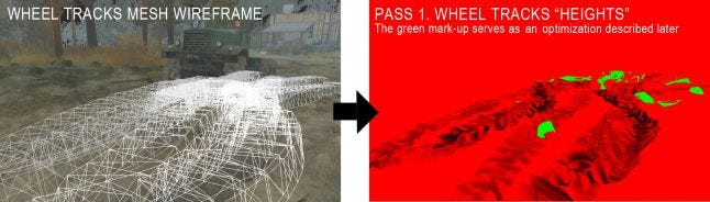
Wheel track heights are required for parallax effect. The textures are projected onto terrain using Z buffer. The tricky part is ordering tracks properly (more recent tracks should cover older tracks). There are several approaches to do this, we use GPU-only method: render tracks with their own z-buffer (so no hardware z-test against scene), and offset more recent tracks towards the camera in vertex shader. Z-test against the scene is performed manually inside pixel shader.
Wheel tracks mesh is then drawn again for a second, final, pass:
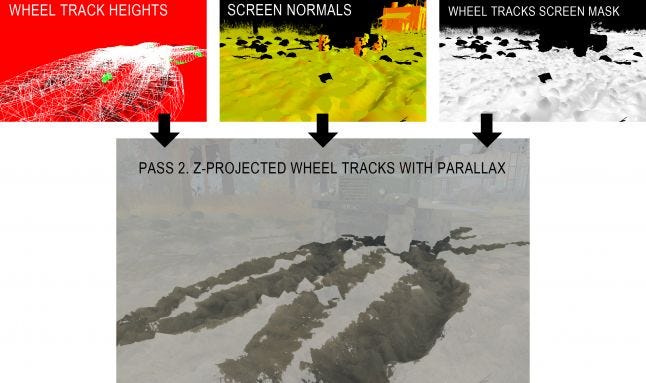
Traditional parallax effect takes multiple sample from associated “heights” texture and then offsets texture coordinates accordingly (we won’t go into details of the math of it). Problem is, if you are z-projecting your texture onto z-buffer, there is no easy way to make said samples. That is why wheel tracks are rendered in 2 passes. The visual artifacts are neglectable with that approach, you just need to make sure you don’t sample from parts of the texture where you don’t have wheel track height info at (that’s what green mark-up of wheel track heights texture is for).
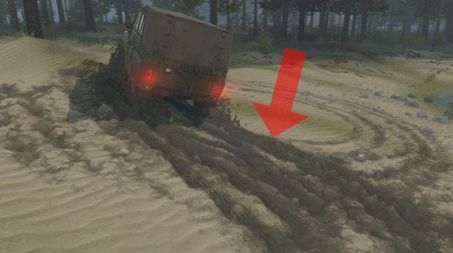
TERRAIN MUD DECALS
When vehicle chassis or wheel moves through the mud at high speed, or when a wheel spins in a mud, it launches mud particles. Mud particles affect per-vertex mud data of most of the environmental assets, and they also generate terrain mud decals:
 Each terrain mud decal has a mesh of oriented box:
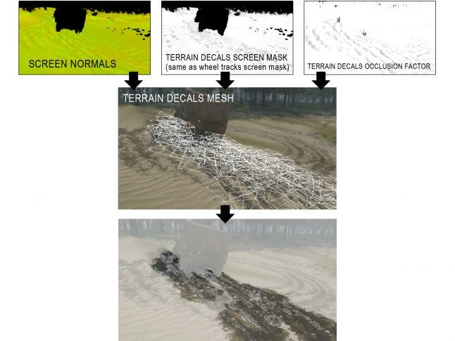
In the same fashion as wheel tracks, after the terrain and most of environment is rendered (it’s called “Color Pass” and it uses MRT – multiple render targets), we have screen normals (used to compute lighting) and terrain decals screen mask (masks out objects that decals shouldn’t be rendered on top of). Color Pass also write occlusion factor for terrain decals so they can be lit more naturally. Decals are z-projected on top of the scene.
Most of the games now feature z-projected decals, so it’s nothing really fancy. Now let's move on to the topic of water...
THE WATER OF MUDRUNNER
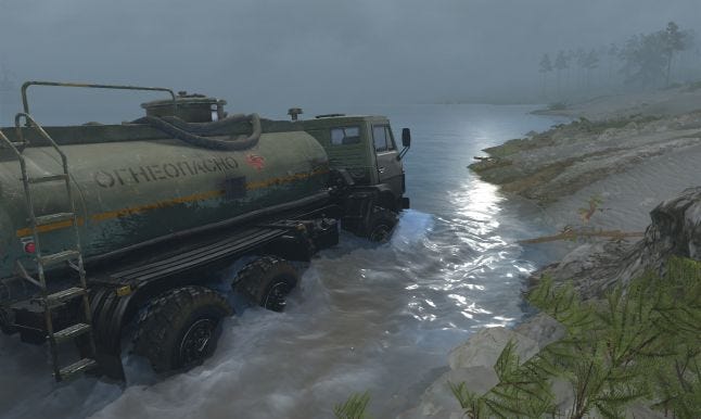
Let’s take a game screenshot and decompose it:
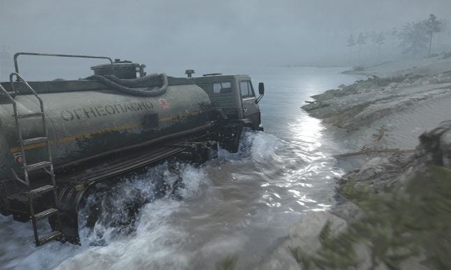
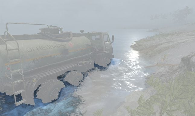
Disable SSAO, FXAA, DOF, Sharpen Effect, Color Correction, Motion Blur and Bloom Effect:
Taking away the layers in the reverse order they are applied:
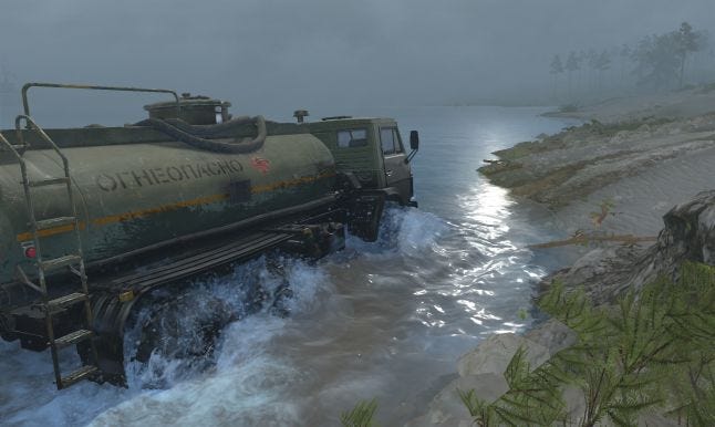
1. Particles
Probably any game has that kind of effect. Particles in MudRunner can be of two types:
“billboard” particles: a quad with spray texture, oriented towards the camera
“subparticles”: small bits of substance that collide against water, terrain and vehicle wheels. Spawned in large quantities (about 14000 on that screenshot!) and are heavily optimized (spawned and deleted in chunks of 16)
LUA scripts are used to spawn the particles. Given wheel and chassis positions, velocities, sizes, current water penetration depth and other parameters, scripts compute initial position and velocity for each particle. Advantage of this approach is that it is very customizable – you can tune particles dynamics in any way you want on the fly. The disadvantage is that this process is very technical.
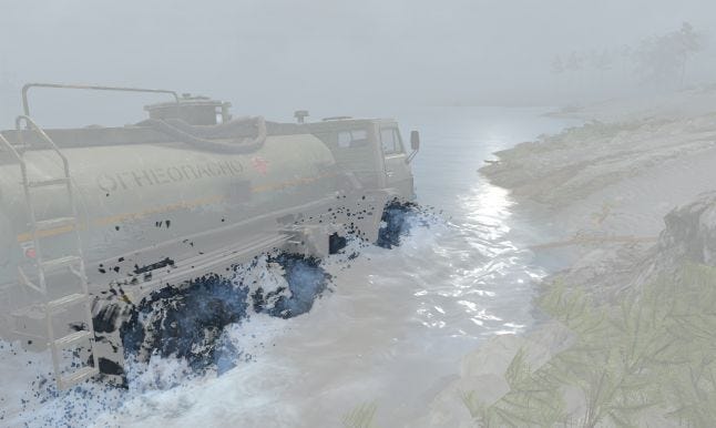
2. Geometric Water Waves
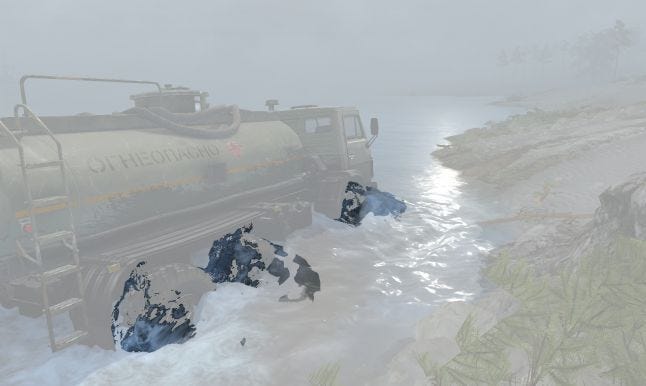
That layer actually consists of 2 different effects, have a look at their wireframes:
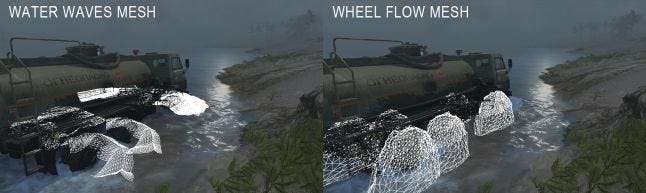
Both meshes are generated on the CPU, with a lot empirical constants involved, and have very vague connection with real world physics of the water.
3. Terrain Wet Decals (will get back to it later)
And now we are left with the water surface itself:
Have a look at its wireframe:
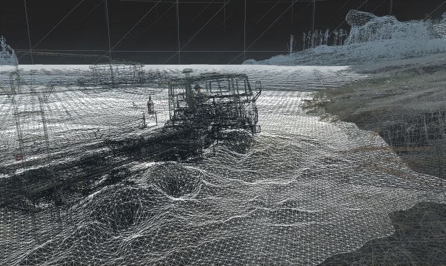
WATER SHADER
Water in MudRunner can flow in different directions, with varying speed, at any angle, it can have different color and transparency, and it can get foamy (when vehicles strike it or simply due to its flow intensity). So how does it work?
Any water shader in any game needs to simulate the water waves. There are many different ways to do this. In MudRunner, as you’ve seen above, the water mesh has relatively high tessellation, so our waves are actually geometric. Most simple way (but far from the most realistic) to render the water waves is to mix several instances of texture like this (MudRunner mixes 5 layers, while applying different texture coordinates scale and offset):
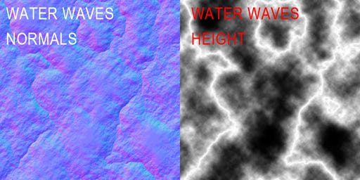
This texture is actually a procedural noise that you can generate in Photoshop. But different character of that texture yields different character of water surface in a game.
But as will be explained later, if you want your water to flow in any direction at any speed, you will actually need to do the above mentioned arithmetic 4 times. And if you want your water to be foamy, you will need to do the whole thing for the foam texture too! And that sums down to a lot of shader arithmetic that just won’t work in real world scenario. MudRunner’s solution is to pre-mix water waves and water foam texture:
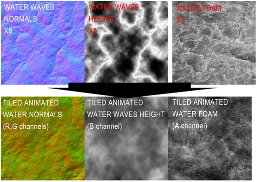
Animated water texture. The only small trick is to make sure those textures can be seamlessly tiled which is easily achieved with some shader math. In the same way, we generate ANIMATED CAUSTICS TEXTURE which we will reference later.
So how do you make your water actually flow? Simple – you scroll the texture coordinates over time. But in which direction, and at what pace? Obviously, that depends on the water direction and water flow speed. In MudRunner, to define water direction and flow speed, map author places “water rivers” in the Level Editor:
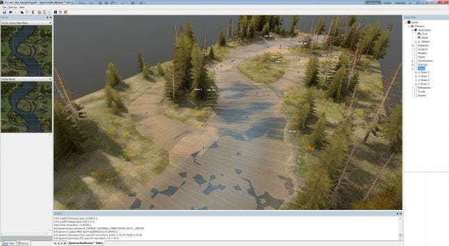
Each “river” is a curve with varying width.
When building a level (preparing it for the game), Level Editor generates continuous water surface by mixing all “water rivers” together:
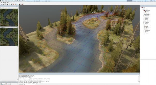
Vertices that define water surface. “Rivers” are not used by the game itself.
Map author uses brush to paint water flow intensity. So in the end, additionally to water surface, Level Editor generates that A8R8G8B8 texture for the game to use when it renders water:
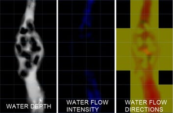
Water data per terrain block (terrain blocks are described in the MUD OF MUDRUNNER paper).
So water shader knows water direction and flow intensity (speed), which is actually merely a 2d vector, let’s call it “flowDir”. They key concept to understanding next step is discretization. It means that we pick one of let’s say 16 possible water directions, a direction that is closest to “flowDir” (let’s call it “flowDir1”), and its “neighbor” direction (“flowDir2”), so that
(here and later HLSL code is used)
flowDir = lerp(flowDir1, flowDir2, flowT);
Where “flowT“ is the interpolation parameter of the two directions.
Having “worldPos” as a world position, water shader can now compute texture coordinates for each direction:
float2 angTC1 = float2(
dot(float2(+flowDir1.x, +flowDir1.y), worldPos.xz),
dot(float2(-flowDir1.y, +flowDir1.x), worldPos.xz));
float2 angTC2 = float2(
dot(float2(+flowDir2.x, +flowDir2.y), worldPos.xz),
dot(float2(-flowDir2.y, +flowDir2.x), worldPos.xz));
Which can actually be used to sample animated water texture (having “g_fTime” as animation time, “tcScale” and “tcScrollSpeed” – arbitrary constants):
float2 tcScroll = float2(g_fTime, 0) * tcScrollSpeed;
float4 waves = lerp(
tex2D(g_samWaves, (angTC1 + tcScroll) * tcScale),
tex2D(g_samWaves, (angTC2 + tcScroll) * tcScale), flowT);
We have omitted the water flow speed discretization for simplicity here, but it follows the same idea, and thus you need the 4 samples to the animated water texture (“g_samWaves” sampler in the code above) which were mentioned earlier.
But the water waves need to be shaded. The recipe for that is pretty common, and it basically involves two components: Reflections and Refractions.
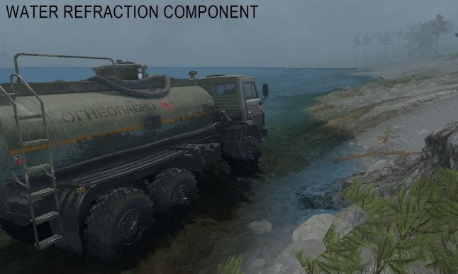
Refractions: objects seen through water. Notice caustics effect that we will get back to later.
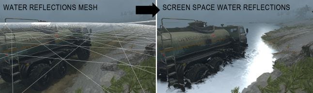
Reflections: objects that are mirrored by the water surface. To render reflections, you can put the camera below water surface and point it upwards (“reflect the camera”), then use technique called “oblique clipping plane”. But that only works well if your water surface is “planar” – which is not the case for MudRunner. MudRunner uses technique called “Screen Space Reflections” (SSR - this technique is well documented in multitude of sources). MudRunner uses SSR only for water reflections, so its version is highly optimized and very lightweight. One of optimizations is, we render the “water reflections mesh” (see picture) instead of full screen quad, so we know position of shaded fragment from vertex shader instead of having to do z-unprojection, and don’t need to do SSR pixel shader for entire screen.
WATER SIMULATION
MudRunner uses a very simple algorithm to compute water simulation, it involves two A8R8G8B8 textures. In the same fashion as mud simulation, we build and draw special primitives into a render target texture:
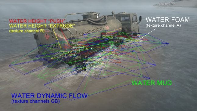
With a knowledge of wheels and chassis positions, their size and velocities, their current water penetration depth, and water speed and direction, CPU forms various “primitives” and draws them into render target textures, which is then read back by GPU. That is pure empirics, and have very vague connection to real world physics of the water!
The first texture with simulation data looks like this:
After the primitives are drawn into that texture, MudRunner performs a “GPU simulation shader” that does a simple propagation of foam, water, height and mud parameters to neighbor texture samples. So two instances of each texture are involved: one for read-back, one for output, and they are swapped each frame.
The second texture only stores “WATER MUD”. Note – there are algorithms that simulate much more realistic water dynamics, but they all require floating point textures for the data, which makes algorithm somewhat more resource-heavy.
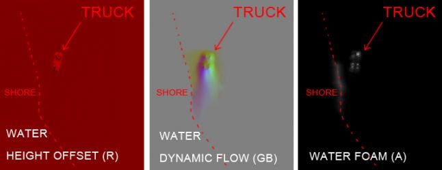
Let’s have a look at another peculiar effect. For the water render pass, we generate special low-res texture, which we call “water domain texture”:
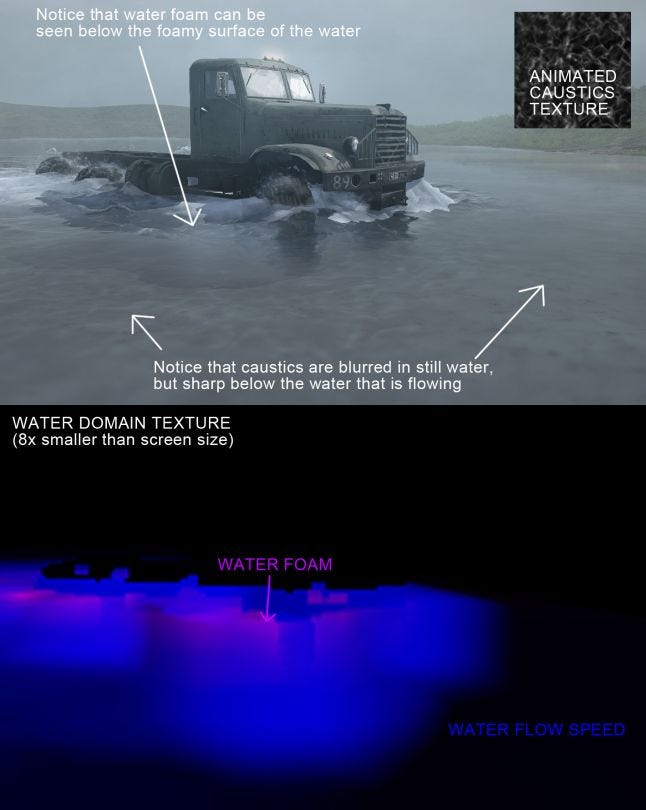
Water domain texture uses a concept, similar to parallax effect, and allows mud (not seen at above picture) and foam to be seen “through” the water. It also stores “water flow speed” that we use to pick the mip level of the “animated caustics texture”. The caustics themselves are simply z-projected when water is drawn. Note that water caustics in MudRunner cannot be seen above the water – drawing the caustics above the water would be a nice improvement in the future!
WATER DECALS
There are 4 types of decals in MudRunner:
Mud decals, produced by “mud” particles and applied to the terrain.
Wet decals, produced by “water” particles and applied to the terrain AND water.
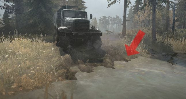
Oil slick decals – produced by working vehicle engine and emulates slick on the water surface, applied to water only.
Dry oil decals – same as oil decals, but emulates oil marks on dry surfaces, so applied to terrain only.
Let’s have a look at oil decals:
The render process is similar to rendering mud decals:
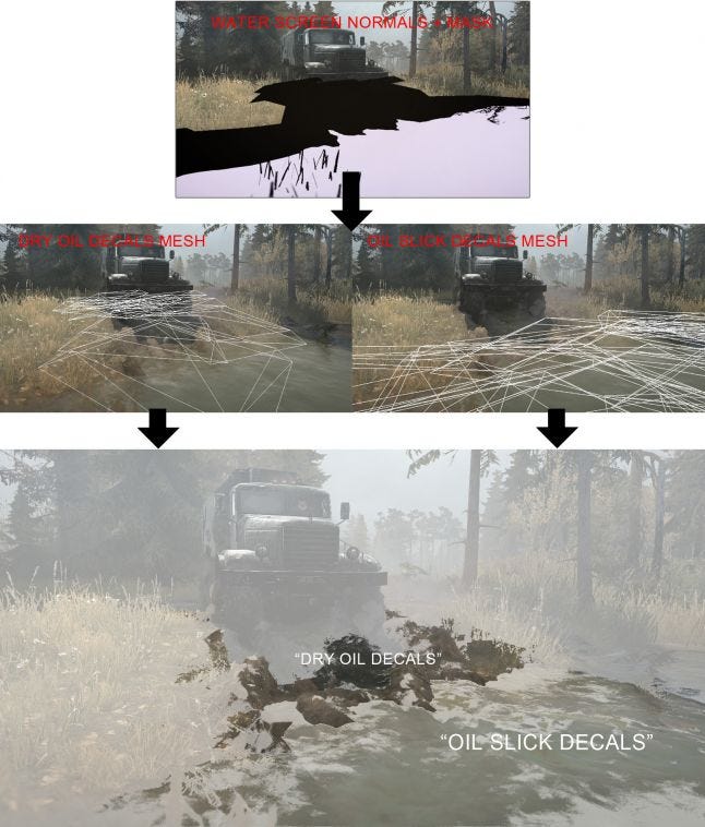
Water needs to output a mask when it’s rendered, so decals can distinguish the surface type they are applied to. Water also writes screen normals that decals use for shading.
That's it for this post, thank you for reading! I hope you enjoyed it!
If you are interested in the game, you can visit MudRunner Official Forum!
Read more about:
Featured BlogsAbout the Author(s)
You May Also Like